Duplexer and communications equipment

A duplexer and passband technology, applied in the field of duplexers, can solve the problems of deterioration of attenuation characteristics, deterioration of transmission signal attenuation characteristics, etc.

Active Publication Date: 2008-07-02
KYOCERA CORP
View PDF1 Cites 23 Cited by
  • Summary
  • Abstract
  • Description
  • Claims
  • Application Information

AI Technical Summary

Problems solved by technology

[0014] However, in this structure, the attenuation characteristic of the transmitted signal deteriorates in a frequency band far from the reception frequency band
This can cause problems, especially with poor attenuation characteristics at frequencies near the low end of the transmit band

Method used


Image

  • Duplexer and communications equipment
  • Duplexer and communications equipment
  • Duplexer and communications equipment

Examples


no. 1 example

[0032] (The principle structure of the duplexer)

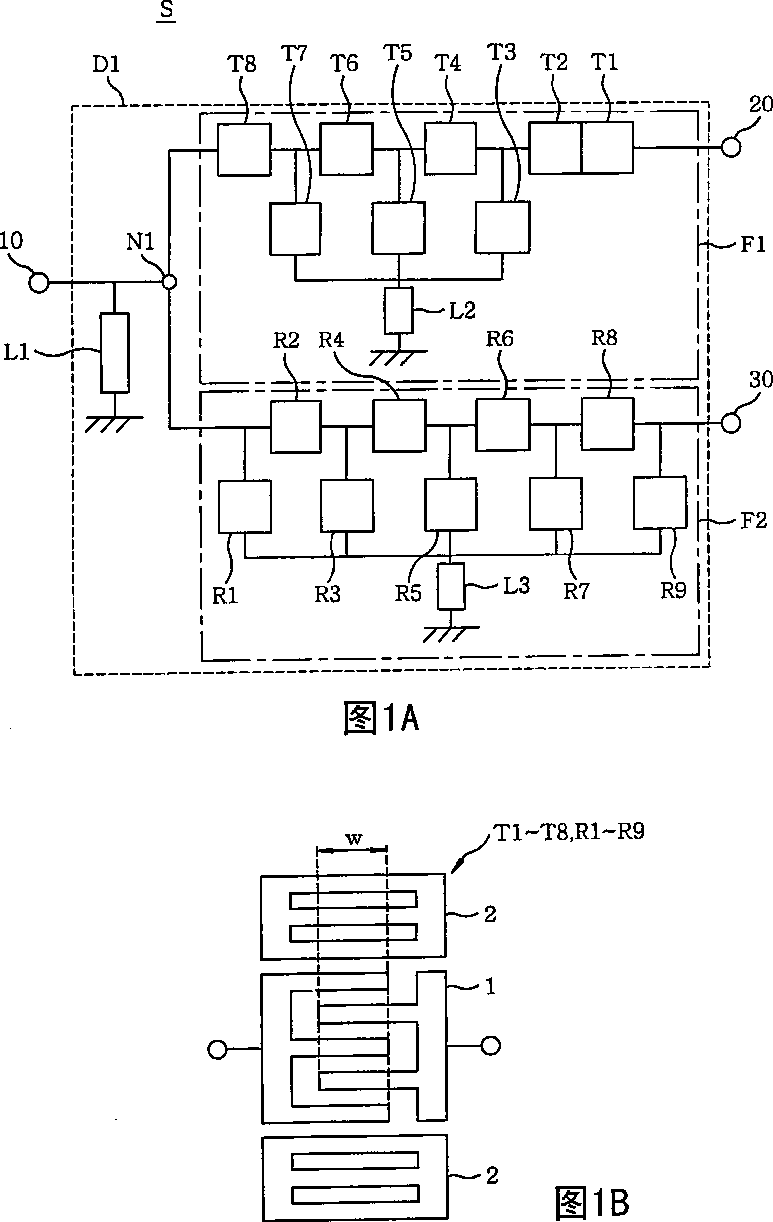
[0033] 1A and 1B are used to explain the duplexer D1 in the first embodiment of the present invention. More specifically, FIG. 1A is a circuit diagram of a duplexer D1, and FIG. 1B is a top view illustrating a representative structure of a resonator from which the duplexer D1 is formed. The structure of the duplexer D1 is such that a transmission filter F1 connected to the transmission terminal 20 and a reception filter F2 connected to the reception terminal 30 are connected to the antenna terminal 10 through a common signal line. The node N1 connects the transmit side end of the transmit filter F1 and the receive side first part of the receive filter F2. The node N1 is also connected to the antenna terminal 10 . In FIG. 1A , the dashed line indicates the area of ​​the duplexer D1, and the dashed-dotted line indicates the areas of the transmit filter F1 and the receive filter F2, respectively. However, these lines do not ac...

no. 2 example

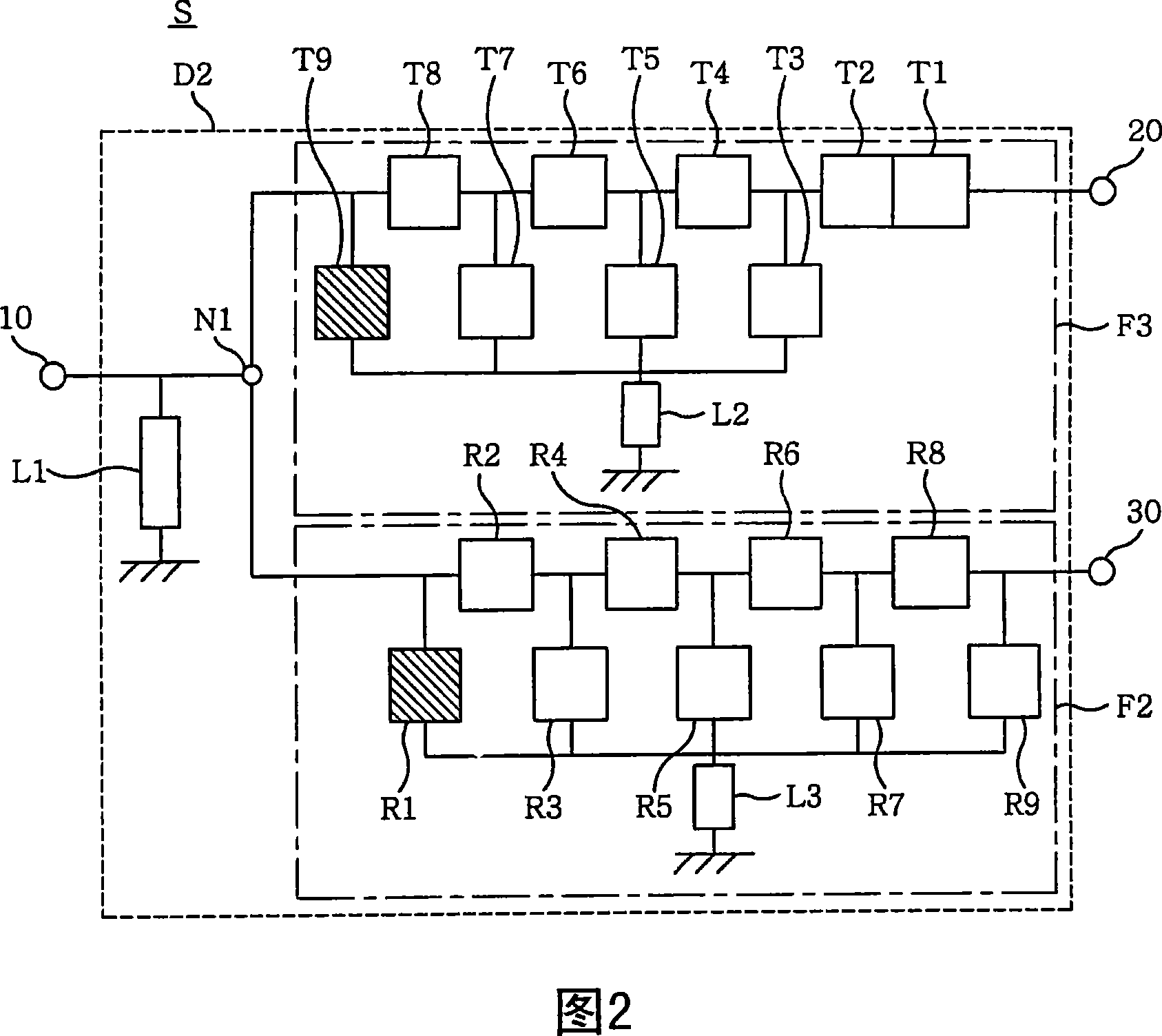
[0067] FIG. 2 is a circuit diagram of a duplexer D2 in a second embodiment of the present invention. The duplexer D2 is configured such that the transmit filter F3 connected to the transmit terminal 20 and the receive filter F2 connected to the receive terminal 30 are connected to the antenna terminal 10 through a common signal line.

[0068] The signal transmission and reception of the duplexer D2 is performed in the same manner as the signal transmission and reception of the duplexer D1 in the first embodiment. That is, the signal (reception signal) received by the antenna terminal 10 is sent to a receiver circuit (not shown) through the reception filter F2 and the reception terminal 30 . Further, a signal (transmission signal) input to the transmission terminal 20 from a transmitter circuit (not shown) is transmitted to the antenna terminal 10 through the transmission terminal F3.

[0069] Furthermore, also in this embodiment, the duplexer D2 is configured such that the pa...

no. 3 example

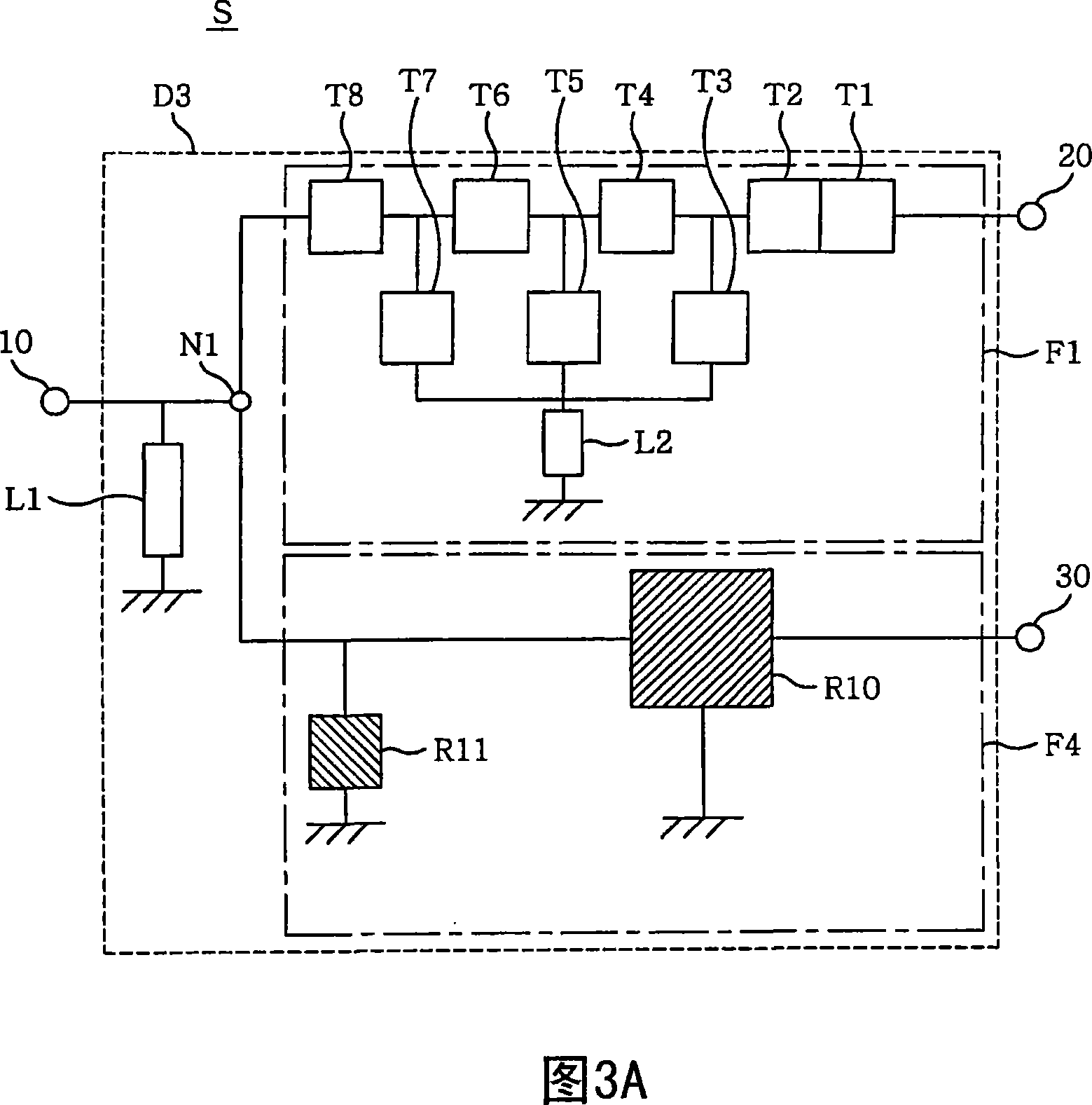
[0079] In the first and second embodiments, the transmission filter and the reception filter are formed using ladder filters. However, the structure of the duplexer in the present invention is not limited to this. 3A and 3B are used to explain the duplexer D3 in the third embodiment of the present invention. Specifically, FIG. 3A is a circuit diagram of the duplexer D3, and FIG. 3B is a schematic top view of a representative structure of a DMS (Dual Mode SAW) filter R10 included in the duplexer D3. The duplexer D3 is configured such that the transmit filter F1 connected to the transmit terminal 20 and the receive filter F4 connected to the receive terminal 30 are connected to the antenna terminal 10 through a common signal line.

[0080] Transmission and reception of signals in the duplexer D3 are performed in the same manner as in the duplexer D1 in the first embodiment. That is, a signal (reception signal) received by the antenna terminal 10 is sent to a receiver circuit (...


PUM


Abstract

A duplexer includes a piezoelectric substrate, a transmitting filter, and a receiving filter. The transmitting filter includes a ladder filter having a first resonator group which has one or more resonators in one or more series arms and one or more resonators in one or more parallel arms. The receiving filter has a passband higher than that of the transmitting filter, and includes a second resonator group which has one or more resonators in one or more series arms and one or more resonators in one or more parallel arms. A node connects both the transmitting filter and the receiving filter. The receive-side closest resonator closest to the node in the parallel arm is closer to the node than a resonator which is closest to the node in the series arm, and a resonance frequency of the receive-side closest resonator is lower than the passband of the transmission filter.

Description

technical field [0001] The present invention relates to a communication device mainly used for mobile communication; in particular, the present invention relates to a duplexer installed therein. Background technique [0002] Recently, as mobile communication terminals tend to be more multi-functional and multi-band, the number of components constituting a so-called RF (Radio Frequency) front end is increasing. On the other hand, there is still a need to keep mobile communication terminals small in size and light in weight. [0003] Furthermore, among the components of a mobile communication terminal, filters are frequently used at a radio frequency level and an IF (intermediate frequency) level. These filters should meet low loss, good out-of-band attenuation characteristics and broadband requirements. [0004] In mobile communication terminals, the duplexer is a component installed just under the antenna. [0005] A duplexer is formed by connecting multiple filters with ...

Claims


Application Information

Patent Timeline
Patent Type & Authority Applications(China)
IPC IPC(8): H03H9/70H03H9/72H03H9/54H03H9/64H03H9/25H03H3/08H03H9/145
CPCH03H9/725H03H9/72
Inventor 伊藤干
Owner KYOCERA CORP
Why Eureka
Try Eureka