Wound coil type inductor

A wire-wound inductor and wire-wound part technology, applied in the direction of inductors, fixed inductors, sensors, etc., can solve the problems of different multiple resonance frequencies, single, etc., and achieve the effect of cost reduction

Inactive Publication Date: 2007-05-23
NOC
View PDF1 Cites 3 Cited by
  • Summary
  • Abstract
  • Description
  • Claims
  • Application Information

AI Technical Summary

Problems solved by technology

[0007] This is different from the above-mentioned type with a constant outer diameter of the magnetic core. As shown in Figure 3, since the outer diameter of the magnetic core gradually decreases, the winding diameter of the wire wound on the magnetic core also gradually decreases. Therefore, although it is an integral winding Wire inductors, but with multiple resonant frequencies not single but different

Method used


Image

  • Wound coil type inductor
  • Wound coil type inductor
  • Wound coil type inductor

Examples


Embodiment 1

[0071] A specific embodiment 1 of the present invention will be described with reference to the drawings.

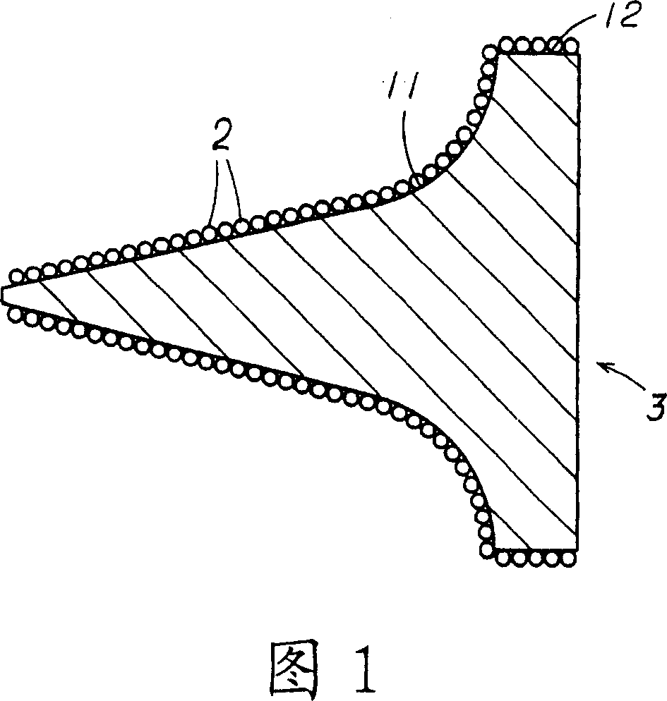
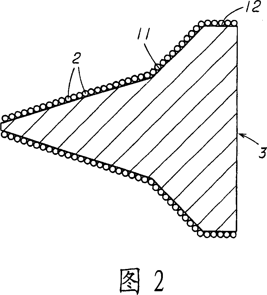
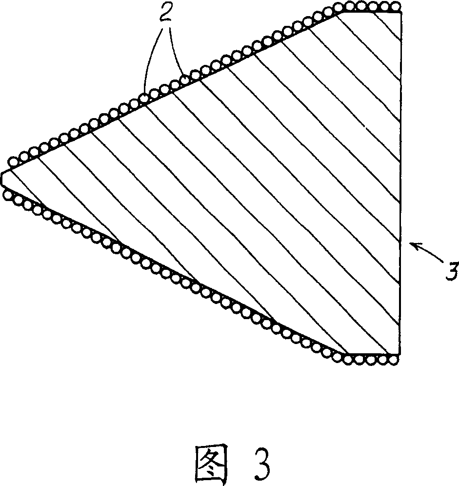
[0072] This embodiment is a wire-wound inductor formed by winding a wire 2 on a magnetic core 3 . In addition, the magnetic core 3 can be made of ferrite or dielectric, and it can also be a magnetic core composed of a mixture of resin and iron powder filled in an air-core coil. As such a wire-wound inductor, a commonly used magnetic core is used. 3. The structure of ferrite is adopted in this embodiment. In addition, a copper wire is used for the wire 2 .

[0073] The magnetic core 3 has a shape having a pointed portion 11 whose outer diameter gradually decreases so that the winding diameter of the above-mentioned wire 2 wound on the magnetic core 3 is not constant but gradually becomes smaller.

[0074]The pointed part 11 formed on this magnetic core 3 is that the outer diameter of the above-mentioned magnetic core 3 is not tapered from the large-diameter base end of ...

Embodiment 2

[0095] A specific embodiment 2 of the present invention will be described with reference to the drawings.

[0096] This embodiment is another example of the above-mentioned embodiment 1. Specifically, as shown in FIG. 6 , a pointed-shaped magnetic core 3 is housed in a case 4 to form a wire-wound inductor.

[0097] Specifically, the above-mentioned magnetic core 3 has a structure in which a non-winding portion 3B on which the above-mentioned wire 2 is not wound is integrally provided on an end portion of the winding portion 3A around which the above-mentioned wire 2 is wound, and by fixing the non-winding portion 3B The case 4 has a structure in which the winding portion 3A of the magnetic core 3 is accommodated in a non-contact state with respect to the case 4 . The connecting terminal portion 5 connected to the circuit wiring of the above-mentioned substrate 1 is provided on the non-winding portion 3B of the above-mentioned magnetic core 3 or the above-mentioned case 4, ther...

Embodiment 3

[0117] A specific embodiment 3 of the present invention will be described with reference to the drawings.

[0118] This embodiment is another example of the above-mentioned embodiment 2. Specifically, as shown in FIG. The structure is as follows: on the outer peripheral surface of the non-winding portion 3B of the magnetic core 3 where the above-mentioned wire 2 is not wound, a reflective member 7 having a higher electromagnetic wave reflection characteristic than the magnetic core 3 is provided along the circumference, and the reflective member 7 is combined with the magnetic core 3. The wire 2 wound on the magnetic core 3 is set in a connected state.

[0119] Therefore, in addition to the attenuation characteristics exhibited by the winding portion 3A of the above-mentioned magnetic core 3, the above-mentioned reflective member 7 also exhibits reflection characteristics, so through the isolation effect of the attenuation characteristics and reflection characteristics, higher...


PUM


Abstract

The present invention provides a wound coil with high attenuation characteristics across a wide frequency band, high uility, and high inducter characteristics across a wide frequency which is not existed so far. The wound coil is made by winding a conductive wire ( 2 ) around a core ( 3 ), wherein the core ( 3 ) is shaped having a tapered part ( 11 ) in which the outside diameter of the core ( 3 ) gradually decreases so that the diameter of the conductive wire ( 2 ) wound around the core ( 3 ) is not constant but instead gradually decreases; and the tapered part ( 11 ) is not tapered so that the outside diameter of the core ( 3 ) decreases at a constant rate from a large proximal end to a small distal end of the tapered part ( 11 ), but rather the tapered part ( 11 ) is formed into a tapered shape wherein the rate of decrease in the outside diameter of the core ( 3 ) is gradually reduced from the large proximal end to the small distal end; i.e., the tapered part ( 11 ) decreases in diameter at a high rate at the proximal end, and decrease in diameter at a lower rate in the distal end than in the proximal end.

Description

technical field [0001] The present invention relates to a wire-wound inductor in which a wire is wound around a magnetic core in order to have inductance. Background technique [0002] Generally speaking, a wire-wound inductor called a magnetic core coil is formed by winding a wire on a magnetic core made of ferrite or a dielectric (others include resin and iron powder filled in an air-core coil). A magnetic core made of a mixture, etc.). [0003] Since the conventional general wire-wound inductor has, for example, a structure in which the above-mentioned wire is wound on the outer peripheral surface of the above-mentioned magnetic core having a constant outer diameter, the winding diameter of the wound wire is also constant, There is therefore only a single resonant frequency for each integral wirewound inductor. [0004] Therefore, the wire-wound inductor with a constant outer diameter of the magnetic core can increase the impedance well in the resonance frequency band a...

Claims


Application Information

Patent Timeline
Patent Type & Authority Applications(China)
IPC IPC(8): H01F37/00H01F27/24H04R9/04
Inventor 小川茂铃木隆一
Owner NOC
Why Eureka
Try Eureka