Anechoic chamber with low frequency shielding property

A technology for radio anechoic chamber and shielding performance, which is applied in the direction of shielding devices to achieve the effects of reducing construction costs, increasing attenuation, good cost performance and promotional value

Active Publication Date: 2012-08-15
YUN NAN ELECTRIC TEST & RES INST GRP CO LTD ELECTRIC INST +1
View PDF5 Cites 7 Cited by
  • Summary
  • Abstract
  • Description
  • Claims
  • Application Information

AI Technical Summary

Problems solved by technology

[0002] There are many types of shielded anechoic chambers, such as full anechoic chambers, semi-anechoic chambers, and other types of anechoic chambers designed to meet the test requirements. Although the test items of different anechoic chambers are different, they generally include the shell shielding shell, The inner wall of the shell is combined with a layer of absorbing material, the door of the anechoic chamber, the turntable of the equipment under test installed in the anechoic chamber and its supporting device, the antenna bracket system, ventilation and lighting equipment, filters, grounding, safety and electrical equipment, measuring instruments and For the interface board connected to the measuring instrument, etc., electromagnetic compatibility tests such as conducted disturbance emission pre-value test, radiated disturbance emission pre-value test, and radiated disturbance immunity test are required to be carried out in an anechoic chamber, but with the development of wave-absorbing material technology Development, the absorption loss of high-frequency electromagnetic waves greater than or equal to 30MHz can be perfectly solved, and the attenuation is above 100dB, but it is difficult to achieve 100dB for electromagnetic wave attenuation between 100kHz-30MHz

Method used


Image

  • Anechoic chamber with low frequency shielding property
  • Anechoic chamber with low frequency shielding property
  • Anechoic chamber with low frequency shielding property

Examples


Embodiment Construction

[0017] In order to make the object, technical solution and advantages of the present invention clearer, the present invention will be further described in detail below in conjunction with the accompanying drawings.

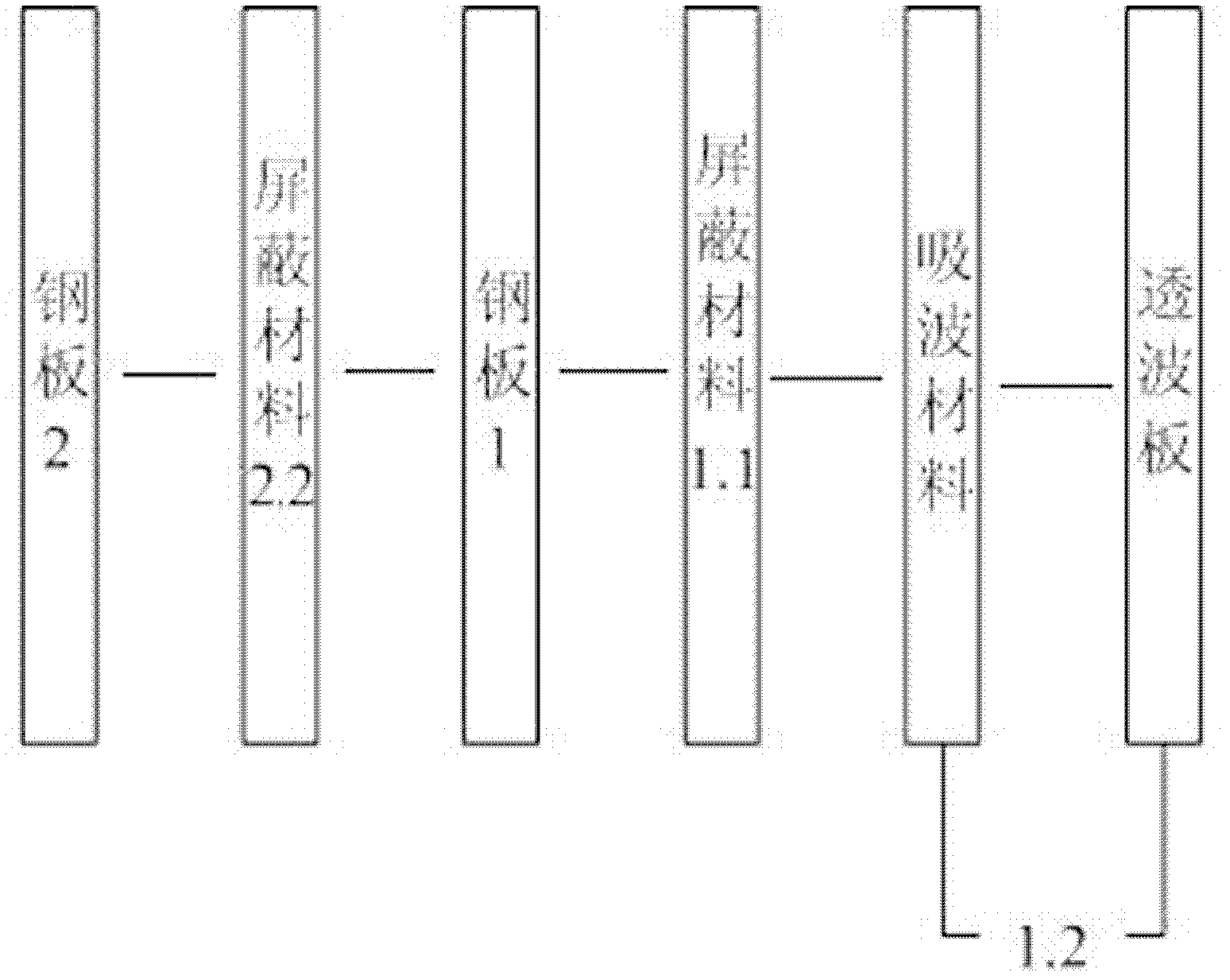
[0018] Such as figure 1 As shown, the double-layer shielding of the present invention consists of 7 parts in total, including the outer shielding steel plate, steel plate 2, shielding material 2, steel plate 1, shielding material 1, wave-absorbing material and wave-transmitting plate. The outer shielding steel plate is As the outermost structure of the anechoic chamber, the steel plate 2 is laid on the inside of the outer shielding steel plate that has been bent on four sides, and the steel plate 2 is fixed on the outer shielding bent steel plate with self-tapping screws, and then the ferrite absorbing material is screwed Fix it on the steel plate 2, and add non-reflective plastic nuts on the top of the screws, among them, in every 600mm*600mm area, there are 4 sc...


PUM


Abstract

The invention relates to an anechoic chamber with low frequency shielding property. The anechoic chamber is of a bilayer shielding structure formed by an inner layer and an outer layer, wherein the inner layer is formed by sequentially laminating a steel plate (1), a shielding material (11), a wave absorbing material and a wave transmitting plate (1.2), leakage of a low frequency electromagnetic field can be effectively avoided, attenuation of the low frequency electromagnetic field is increased, technical indexes of the anechoic chamber in the field of low frequency are obviously improved, the anechoic chamber is simple and feasible, construction cost of the anechoic chamber is reduced, and the anechoic chamber has relatively good cost performance and promotional value.

Description

technical field [0001] The invention belongs to the technical field of an anechoic chamber with low-frequency shielding performance, in particular to the structure of an anechoic chamber with excellent low-frequency shielding performance. Background technique [0002] There are many types of shielded anechoic chambers, such as full anechoic chambers, semi-anechoic chambers, and other types of anechoic chambers designed to meet the test requirements. Although the test items of different anechoic chambers are different, they generally include the shell shielding shell, The inner wall of the shell is combined with a layer of absorbing material, the door of the darkroom, the turntable of the equipment under test installed in the darkroom and its supporting device, the antenna bracket system, ventilation and lighting equipment, filters, grounding, safety and electrical equipment, measuring instruments and For the interface board connected to the measuring instrument, etc., electr...

Claims


Application Information

Patent Timeline
Patent Type & Authority Applications(China)
IPC IPC(8): G01R1/18
Inventor 丁心志毕志周曹敏梁仕斌杨林林
Owner YUN NAN ELECTRIC TEST & RES INST GRP CO LTD ELECTRIC INST
Why Eureka
Try Eureka