Network node and buffer device, and scheduling method

A technology of network nodes and scheduling methods, applied in the field of optical networks, can solve the problems of data packets can only be discarded, difficult to integrate, and blocked at the head of the queue, and achieve the effect of reducing the scale, reducing the scale and reducing the loss rate.

Inactive Publication Date: 2008-07-02
HUAWEI TECH CO LTD +1
View PDF0 Cites 11 Cited by
  • Summary
  • Abstract
  • Description
  • Claims
  • Application Information

AI Technical Summary

Problems solved by technology

The disadvantage of this feed-forward connection scheme is: a dedicated multi-level FDL is configured for each wavelength, and the number of FDLs required is large, resulting in a large scale of core nodes, and a single-plane switch matrix structure, that is, a PM×PM scale switch matrix structure , the switching matrix is ​​composed of switches, if represented by 1×2 basic optical switches, the number of basic optical switches needs to be 2×PM(PM-1), so the scale of the core nodes is larger and it is difficult to integrate and realize; Because the cache adopts a linear connection structure, the number of FDLs is limited, and there is an upper limit of th

Method used


Image

  • Network node and buffer device, and scheduling method
  • Network node and buffer device, and scheduling method
  • Network node and buffer device, and scheduling method

Examples


Embodiment Construction

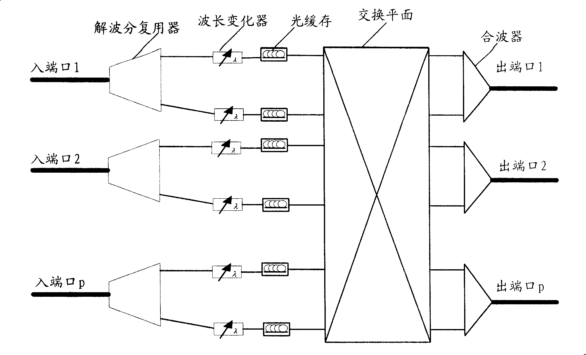
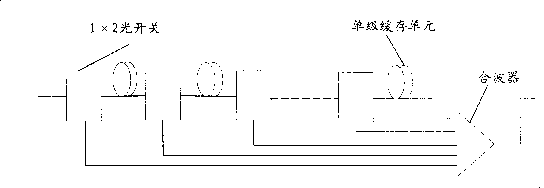
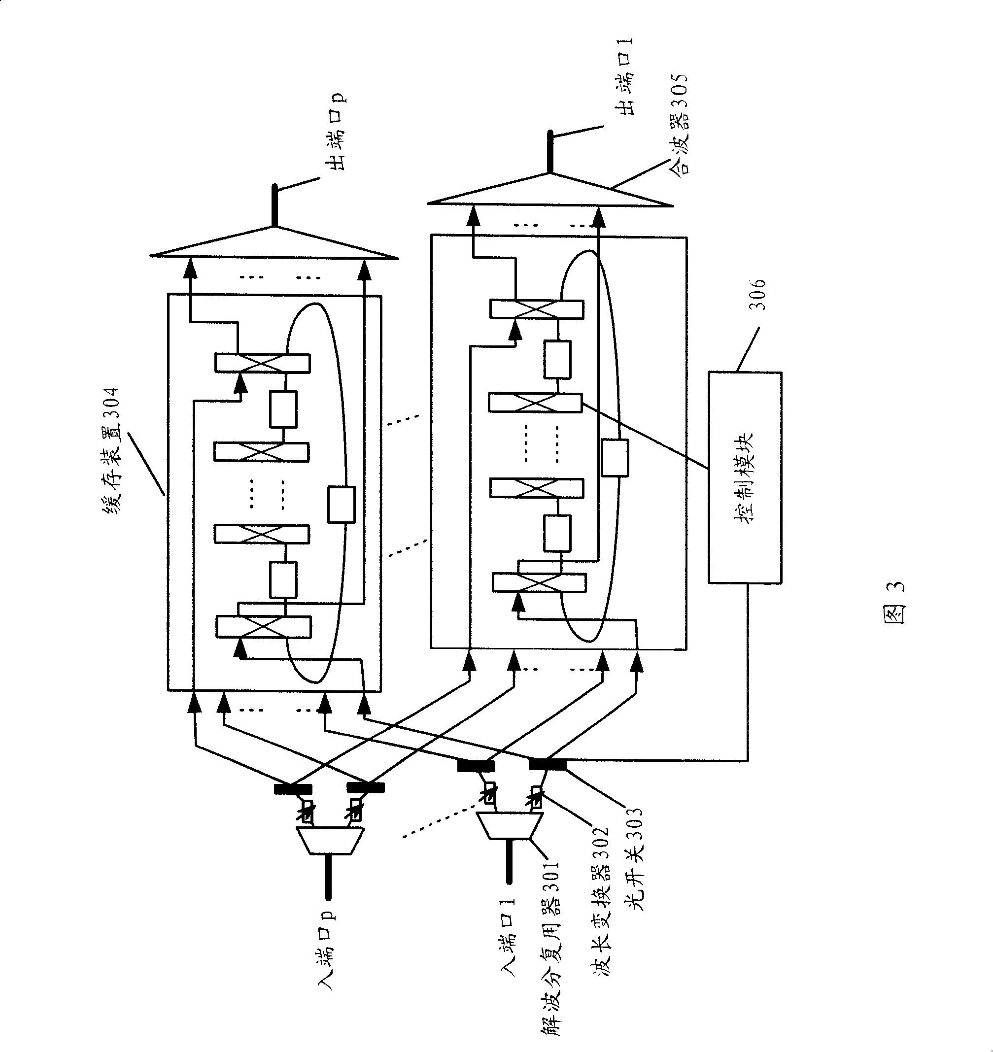
[0049] The present invention provides a cache device, including at least one internal switching unit and at least one basic cache unit, the internal switching unit includes at least two input terminals and two output terminals, and the internal switching unit passes the two input terminals One of the input terminals, one of the two output terminals and the basic buffer unit are spaced apart to form a closed connection, the other input terminal of the internal switching unit receives light waves, and the internal switching unit according to the first control A signal outputs the light wave, and the basic buffer unit is used for buffering the light wave from the internal switching unit. At the same time, the present invention also provides a network node and a scheduling method. In order to make the technical solution of the present invention clearer, the following describes the present invention in detail with reference to the accompanying drawings and examples.

[0050] Referr...


PUM


Abstract

The invention discloses a buffering device which comprises at least one internal conversion unit and at least one basic buffering device. The internal conversion unit at least comprises two input ends and two output ends. The internal conversion unit is connected with the basic buffering device in close way at intervals through one input end of the two input ends and one output end of the two output ends. The other input end of the internal conversion unit receives light waves; the internal conversion unit outputs the light waves according to a first control signal and the basic buffering device is used for buffering the light waves from the internal conversion unit. Meanwhile, the invention further provides a network node and a regulating method. By employing the technical proposal of the invention, the scale of the network node is small, thus being easy for practice, reducing loss rate of data packets as well as avoiding blocking of head of line at the same time.

Description

technical field [0001] The invention relates to the technical field of optical networks, in particular to a network node, a cache device and a scheduling method in an optical packet switching network. Background technique [0002] With the rapid growth of packet services, future communication network design should focus on optimizing packet support. Optical network packet switching technology can broaden the existing network bandwidth, and network nodes have high information throughput, suitable for supporting burst Packet services with strong characteristics and frequent service changes, especially IP services. [0003] Now, the optical packet switching network is generally composed of edge nodes and core nodes, which are connected by dense wavelength division multiplexing DWDM fiber links, and data packets are transmitted from edge nodes to core nodes through DWDM fiber links, and then exchanged The modules are exchanged and finally sent to the destination edge node. [...

Claims


Application Information

Patent Timeline
IPC IPC(8): H04Q11/00H04L12/56
CPCH04J14/0227H04Q2011/0016H04Q11/0005H04J14/0283H04J14/0246H04Q2011/002H04J14/0212H04J14/0254H04J14/0256
Inventor 张毅潘永康苏清博王晟许都
Owner HUAWEI TECH CO LTD
Why Eureka
Try Eureka