Magnetic encoder

A magnetic encoder and magnetic sensor technology, applied in the field of magnetic encoders, can solve the problems of decreased detection accuracy and the inability of the magnetic field to reach the saturation sensitivity region, etc.

Active Publication Date: 2008-07-02
NIDEC SANKYO CORP
View PDF3 Cites 23 Cited by
  • Summary
  • Abstract
  • Description
  • Claims
  • Application Information

AI Technical Summary

Problems solved by technology

[0013] However, as shown in FIG. 11( b ), when the linear encoder 201 is constructed so that the sensor surface 216 faces in a direction perpendicular to the permanent magnet 220, there is a region where the magnet

Method used


Image

  • Magnetic encoder
  • Magnetic encoder
  • Magnetic encoder

Examples


Embodiment Construction

[0044] The best mode for carrying out the present invention will be described with reference to the drawings.

[0045] [Embodiment 1]

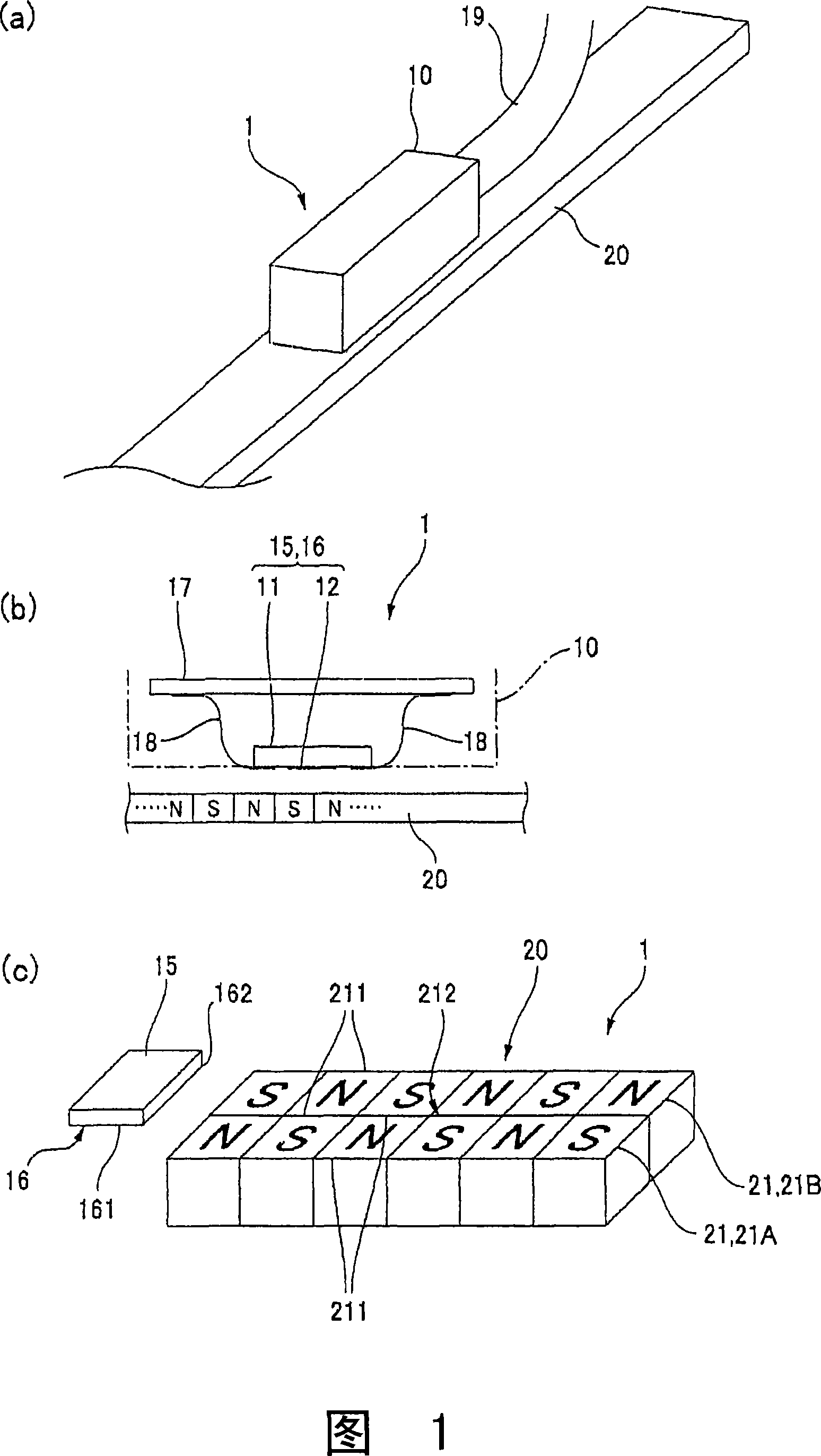
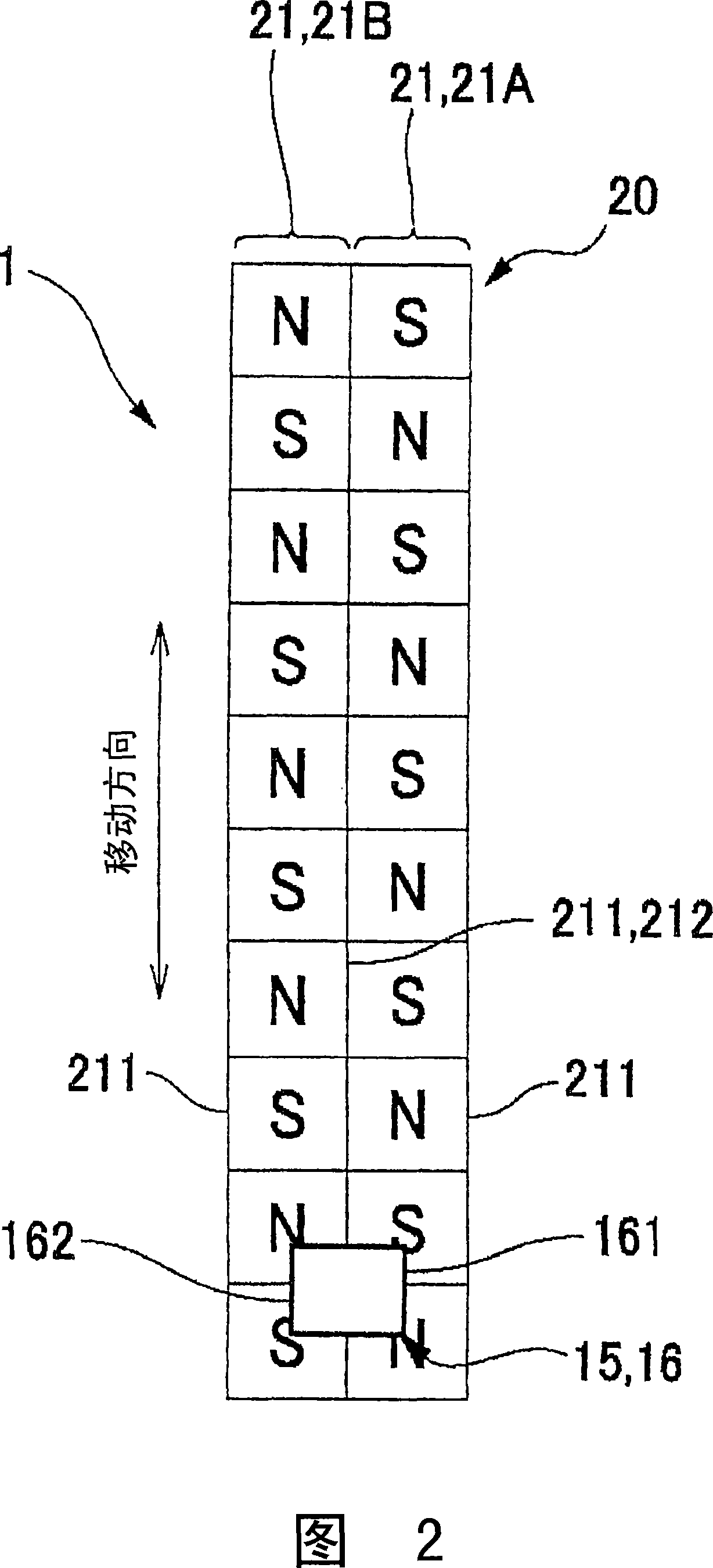
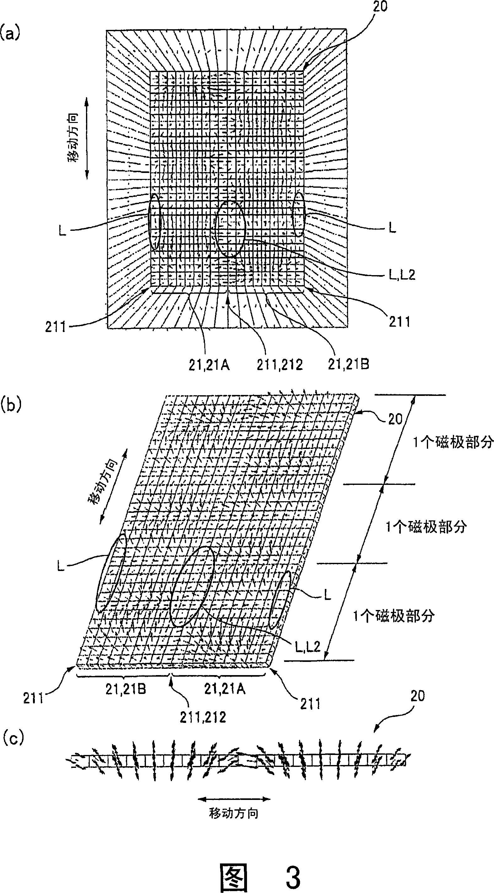
[0046] 1( a ), ( b ) and ( c ) are a perspective view schematically showing the structure of a magnetic encoder (linear encoder) to which the present invention is applied, a cross-sectional view, and an explanatory view showing its principle, respectively. Fig. 2 is an explanatory view showing a planar positional relationship between a permanent magnet and a magnetic sensor in the magnetic encoder according to Embodiment 1 of the present invention. 3(a), (b), and (c) are explanatory diagrams when viewing the direction of the magnetic field formed by the permanent magnet on a plane, respectively, in the magnetic encoder related to Embodiment 1 of the present invention. An explanatory diagram when viewed, and an explanatory diagram when viewed from the side.

[0047]As shown in Fig. 1 (a), (b), and (c), the magnetic encoder 1 of this form has:...


PUM


Abstract

In a magnetic encoder (1), a permanent magnet (20) as a magnetic scale is provided with three rows of tracks (21) wherein N poles and S poles are alternately arranged along a shift direction. In the permanent magnet (20), at end portions (211) in the width direction of the tracks (21A, 21B, 21C), a rotating magnetic field wherein a planar direction changes is formed, and a sensor plane (16) of a magnetic sensor (15) faces a boundary portion (212) between the tracks (21A, 21B, 21C). Thus, detection accuracy of the magnetic encoder of the rotating magnetic field detection type is improved.

Description

technical field [0001] The present invention relates to a magnetic encoder comprising: a magnetic sensor with a magnetoresistive element on a sensor surface, and a permanent magnet that moves relative to the magnetic sensor. Background technique [0002] The magnetic encoder includes: a magnetic sensor with a magneto-resistive element on the sensor surface, and a permanent magnet that moves relative to the magnetic sensor. On the permanent magnet, a magnetic track with N poles and S poles alternately arranged along the moving direction (for example, Refer to Patent Documents 1, 2, and 3). [0003] There are generally two types of such magnetic encoders, one is the type that detects the position according to the strength of the magnetic field in a certain direction, and the other is the type that detects the direction of the rotating magnetic field by the magnetic field strength above the saturation sensitivity area. The latter is a representative type of magnetic encoder, w...

Claims


Application Information

Patent Timeline
IPC IPC(8): G01D5/245G01D5/244
CPCG01D5/2451G01D2205/80
Inventor 有贺英吉森山克也野口直之
Owner NIDEC SANKYO CORP
Why Eureka
Try Eureka