Wireless communication apparatus

A technology for wireless communication systems and equipment, applied in the directions of diversity/multi-antenna systems, baseband system components, multi-frequency code systems, etc.

Inactive Publication Date: 2008-07-02
KK TOSHIBA
View PDF0 Cites 6 Cited by
  • Summary
  • Abstract
  • Description
  • Claims
  • Application Information

AI Technical Summary

Problems solved by technology

However, none of the above literature discusses the principle of applying the LLL algorithm or any other lattice reduction algorithm to groups of subcarriers

Method used


Image

  • Wireless communication apparatus
  • Wireless communication apparatus
  • Wireless communication apparatus

Examples


Embodiment Construction

[0058] The invention will now be described in more detail with reference to the accompanying drawings.

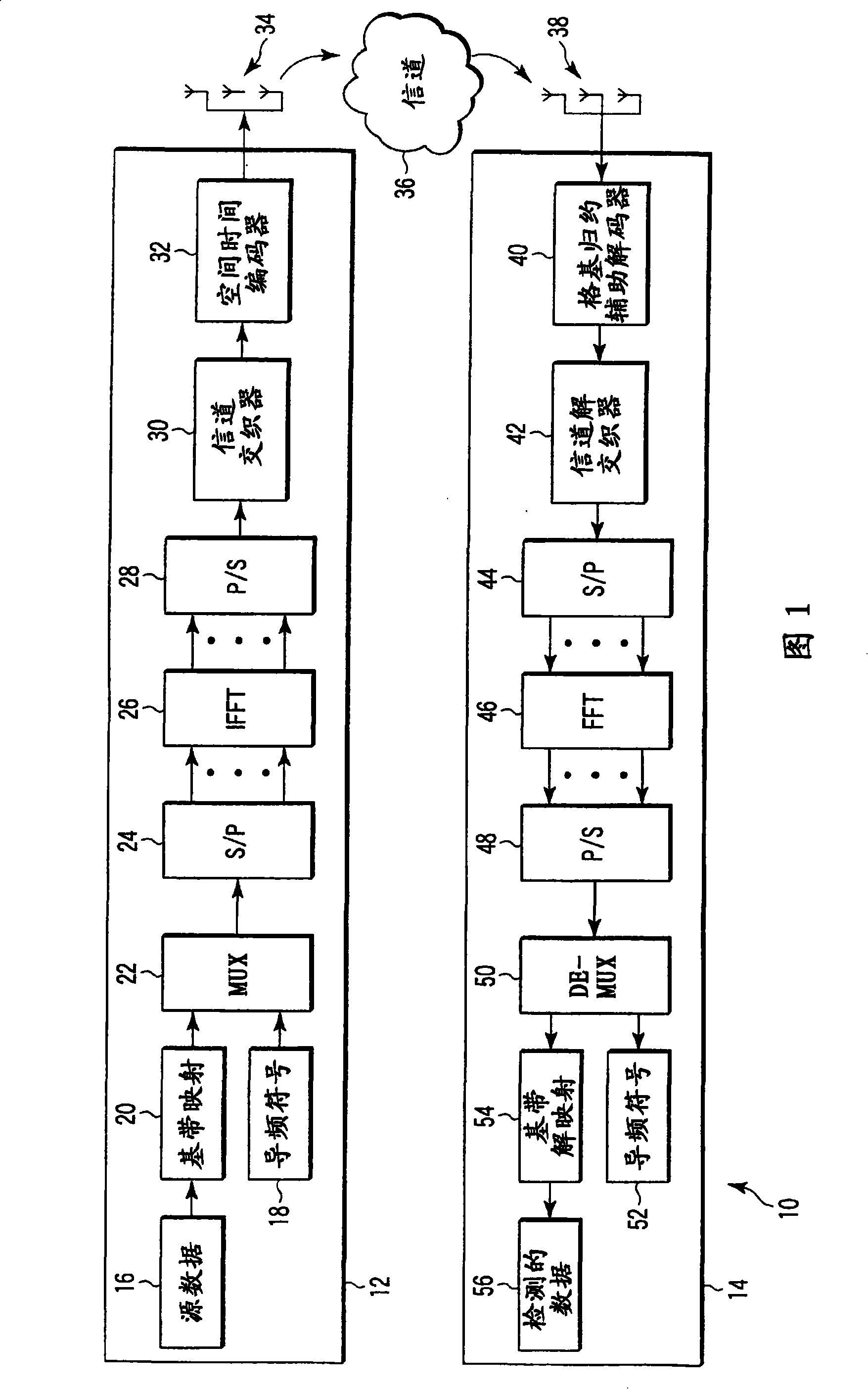
[0059] Figure 1 shows such a system comprising a MIMO data communication system 10 having a well-known structure. Novel components according to specified embodiments of the present invention will become apparent from the following description.

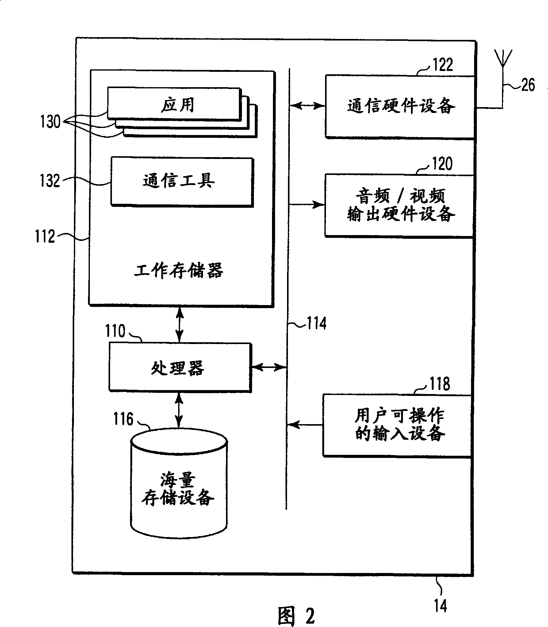
[0060] Communication system 10 includes sending device 12 and receiving device 14 . It should be appreciated that in many cases wireless communication devices have combined transmitter and receiver equipment, but in this example the device is shown as a one-way communication device for simplicity.

[0061] Transmitting device 12 includes a data source 16 which provides data, including information bits, to a baseband mapping unit 20 which optionally provides forward error correction coding and channel interleaving and outputs modulated symbols. The modulated symbols are provided to a multiplexer 22 which combines the modulated symb...


PUM


Abstract

This invention relates to methods, apparatus, and processor control code for signal detection in Multiple Input Multiple Output Orthogonal Frequency Division Multiplexed (MIMO-OFDM) communications systems. A method for determining outputs from a received signal in a lattice-reduction-aided receiver based multi-carrier wireless communications system having a plurality of sub-carriers divided into a plurality of sets of sub-carriers, the method comprising performing a detection method for each of said sets, the detection method comprising the step of applying lattice reduction to said set of sub-carriers thereby generating a reduced basis channel response.

Description

technical field [0001] The present invention relates to methods, devices and processor control codes for signal detection in multiple-input multiple-output (MIMO) communication systems. More specifically, the present invention relates to signal detection in MIMO Orthogonal Frequency Division Multiplexing (MIMO-OFDM) communication systems. Background technique [0002] A traditional communication system can be expressed mathematically as: [0003] y=Hx+v [0004] where, for a MIMO communication system, y is an n×1 vector representing the received signal, H is an n×m channel matrix that simulates the transmission characteristics of the communication channel, x is an m×1 vector representing the transmitted symbols, and v is an n× 1 noise vector, and where m and n denote the number of transmit and receive antennas, respectively. [0005] Recent publications have shown how the performance of MIMO detection methods can be improved using a technique called Lattice Reduction. ...

Claims


Application Information

Patent Timeline
Patent Type & Authority Applications(China)
IPC IPC(8): H04L25/02
CPCH04L25/0246H04L27/2647H04B7/08H04L25/02H04L27/26
Inventor A·G·利利D·P·麦克纳马拉M·S·T·桑德尔
Owner KK TOSHIBA
Why Eureka
Try Eureka