
Surrounding type non-contact wiping-free car washing machine

A wiping-free, car-washing technology, which is applied to the vehicle exterior cleaning device and other directions, can solve the problem of not being able to detect the width of the vehicle body, and achieve the effect of accurate spray position.

Inactive Publication Date: 2008-07-09
黄岳良 +1
View PDF0 Cites 18 Cited by
  • Summary
  • Abstract
  • Description
  • Claims
  • Application Information

AI Technical Summary

Problems solved by technology

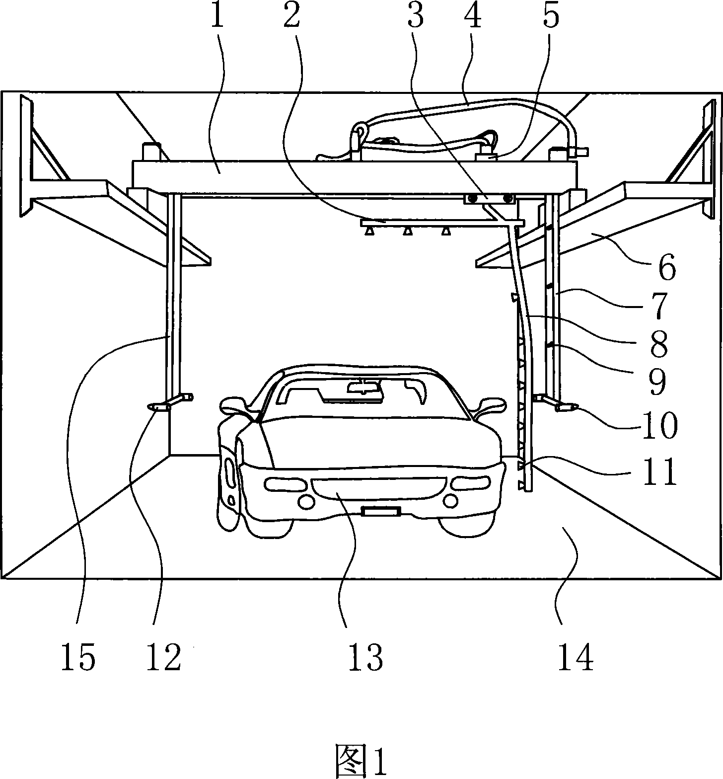
[0002] The current fully automatic computer car washing machine, see Figure 1: mainly includes longitudinal guide rail 6, beam 1, L-shaped liquid spray frame 2 and 8, water nozzle 11, washing liquid nozzle 9, infrared electronic beam-to-radio probe mounting frame 7 and its Infrared electronic cross-shooting probes 10 and 12, lateral moving device 3 of the liquid spraying frame, PLC programmable controller, rotary motor 5 of the liquid spraying frame and its infusion tube, the crossbeam 1 can move longitudinally on the longitudinal guide rail 6, and the liquid is sprayed from the top The L-shaped liquid spray frame composed of the rod 2 and the liquid spray side rod 8 can rotate 360 ​​degrees under the control of the PLC programmable controller and move laterally on the beam 1. The liquid spray rod 2 on the top and the liquid spray side rod 8 is provided with a water nozzle 11, and a washing liquid nozzle 9 is installed on the mounting bracket 7 at one end of the laterally moving guide rail. The water nozzle 11 and the washing liquid nozzle 9 are connected to the water pump and the washing liquid pressure pump through the infusion tube 4. The electronic anti-radiation probes 10 and 12 are respectively arranged on the lower ends of the two suspension frames 7 hanging downwards at the two ends of the beam 1, and a washing liquid nozzle 9 is installed on one suspension frame 7, and the infrared electronic anti-radiation probes 10 and 12 The transmitting head and the receiving head shoot to form a detection line to measure whether the head or tail of the vehicle 13 is still in the spraying range of the water nozzle 11 and the washing liquid nozzle 9, if not in the range, that is, when the vehicle body no longer blocks the detection line, Then the PLC programmable controller controls the spraying frame 2 and 8 to rotate, and its weak point: the one, the infrared electronic cross-shooting probe 10,12 can only detect the vehicle body length, can not detect the vehicle body width: utilize the infrared electronic cross-shooting that the above-mentioned method is installed Probes 10 and 12 can only detect whether the vehicle body is still in the longitudinal injection range where the water spray nozzle 11 and the washing liquid nozzle 9 are located by blocking the infrared rays sent by the detection head by the vehicle body, if not in the detection range, the L-shaped liquid spray frame is controlled to rotate; The rotation of the L-shaped liquid spray frame can only do longitudinal movement, and horizontal movement when rotating and rotating. When the L-shaped liquid spray frame moves longitudinally, it cannot do horizontal movement, resulting in uneven and incomplete cleaning of the body surface: because when When the vehicle is parked at an incline, that is, when the vehicle is not parked in the specified car washing position, the distance between the outer surface of the vehicle body and the liquid spraying side bar 8 is different, which not only makes the cleaning liquid and cleaning water spray unevenly, but also makes the vehicle not thoroughly cleaned, and is easy to damage the vehicle. body surface, causing vehicle damage or increased maintenance costs, and the third is that the spraying position of the washing liquid is limited: because the washing liquid nozzle 9 is installed on the vertical suspension frame 7 at one end of the beam 1, it cannot move laterally and rotate. When the vehicle 13 to be cleaned When parked in the car wash room 14 away from the side of the washing liquid nozzle 9 or when the vehicle 13 is parked obliquely, the washing liquid cannot all be sprayed onto the vehicle body. The effect of spraying liquid on the side of the car body is good, but the spraying liquid on the roof part is not uniform; the fourth is that the water pressure sprayed by the water nozzle lacks the difference in size: generally the lower part of the side of the car body is dirty, and a higher pressure water pressure is needed for spray cleaning would be better, but existing equipment cannot

Method used


Image

  • Surrounding type non-contact wiping-free car washing machine
  • Surrounding type non-contact wiping-free car washing machine
  • Surrounding type non-contact wiping-free car washing machine

Examples


Embodiment 1

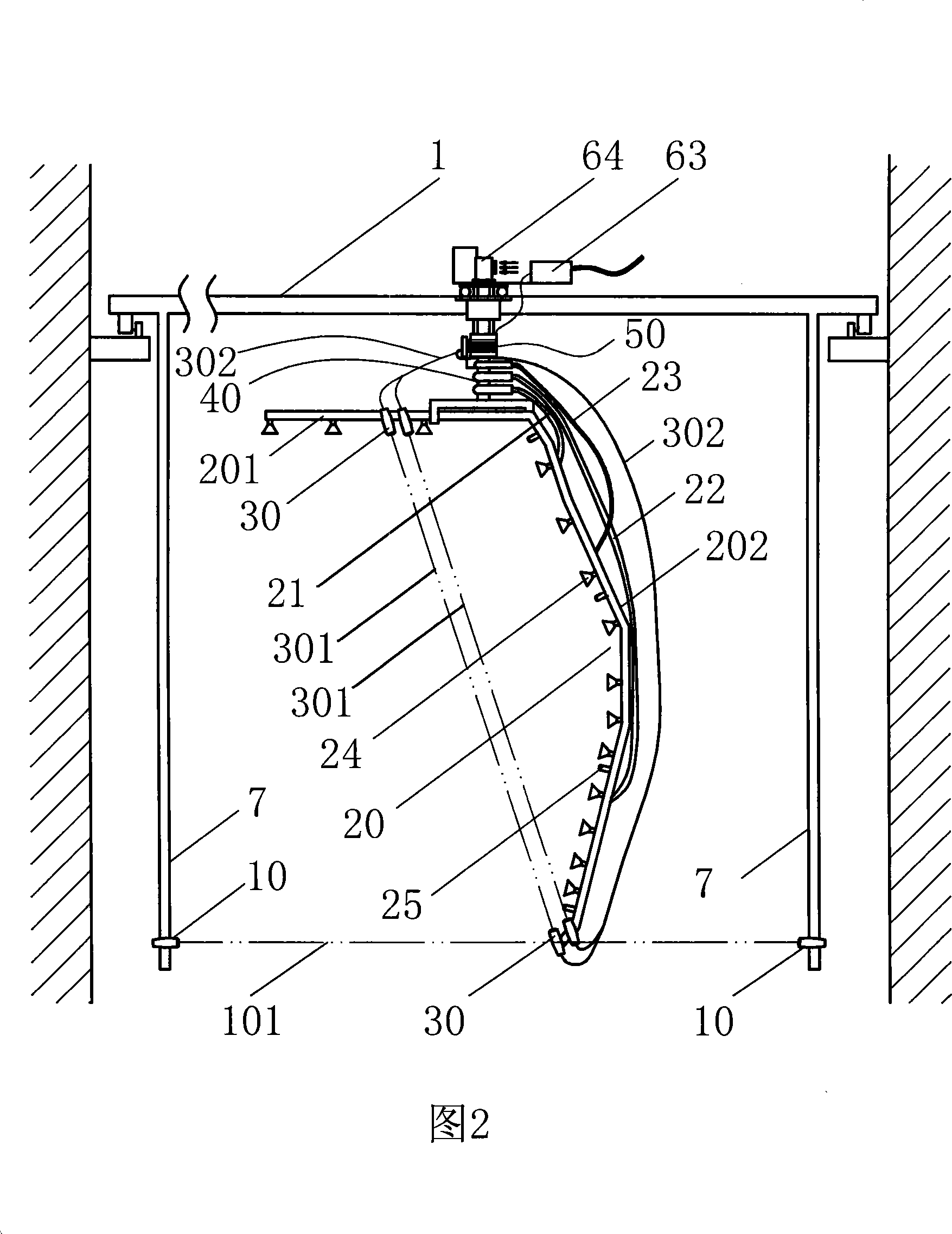
[0023] Embodiment 1: Refer to Fig. 2, Fig. 4-7: Surrounding type non-contact and wipe-free car washing machine, including two pairs of infrared electronic anti-radiation probes 10 and The bow-shaped liquid spraying frame 20 composed of the top liquid spraying rod 201 and the liquid spraying side rod 202 is provided with a water nozzle 24 on the liquid spraying frame 20, and the liquid spraying frame 20 can be moved longitudinally and laterally under the drive of the motor. The longitudinal axis of the liquid spray frame is rotated 360 degrees, and at the middle part of the top liquid spray rod 201 and the lower end of the liquid spray side rod 202, two pairs of infrared electronic probes 30 that can transmit and receive signals are installed respectively. When the shooting probe 30 shoots against each other, two detection lines 301 separated by a certain distance can be formed in the plane formed by the bow-shaped liquid spray frame 20. The signal line of the infrared electroni...

Embodiment 2

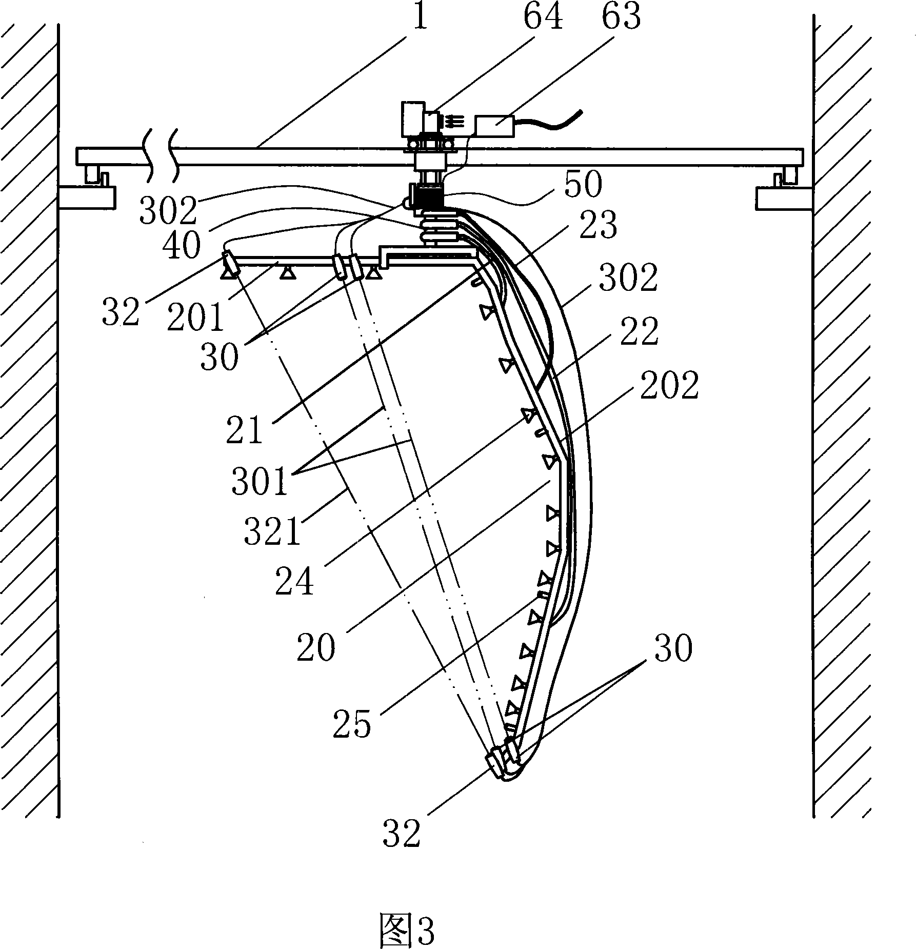
[0026] Embodiment 2: Refer to Fig. 3, Fig. 4-7: the basic structure is the same as that of Embodiment 1, the difference is that: the two hangers 7 lower ends of the two suspension frames 7 that are installed on the two ends of the crossbeam 1 and hang down as described in Embodiment 1 A pair of infrared electronic shooting probes 32 arranged at the two ends of the spray frame 20 replace the infrared electronic shooting probe 10, and the detection line 321 formed by a pair of infrared electronic shooting probes 32 is responsible for detecting the front and the rear of the vehicle. And the detection signal is sent to the PLC programmable controller so as to control the rotation of the liquid spray frame 20, and spray liquid to clean the front and rear of the vehicle.

[0027] Working process and principle of the present invention:

[0028] 1. When the vehicle enters the car wash room, under the control of the PLC programmable controller, the water wall formed by the water nozzle...


PUM


Abstract

The invention relates to the vehicle spraying equipment technology and discloses a surround non-contact wipe-free car washer. An infrared electronic opposite type detection probe for detecting the distance between a vehicle body and a liquid spray bracket is positioned at the middle of a top spray rod and the lower end of the liquid spray side rod. An infrared electronic radio detection probe for detecting the length of the vehicle body is positioned at the two ends of the liquid spray bracket or the lower end of two suspension brackets hanging downward the two ends of a cross beam. A water sprayer connecting with a low-pressure water pipe and a high-pressure water pipe and a washing solution sprayer connecting with a washing solution pipe are positioned on the liquid spray bracket respectively. The detection line of the water sprayer, the washing solution sprayer and the infrared electronic radio detection probe is transferred via a liquid switchover valve and a signal transferring device for enabling the liquid spray bracket to do the continuous rotation of more than 360 degree. The action of the liquid spray bracket, a water pump and the washing solution are controlled by a PLC (programmable logic controller). The invention has the advantages of the accurate positioning of spraying location, the clean washing, the continuous rotation of the liquid spray bracket, no touch on the vehicle body and being suitable for wide application on the automatic car washer with various specifications and types.

Description

Technical field: [0001] The invention relates to the technical field of vehicle spray washing equipment, in particular to a surrounding non-contact and wiping-free car washing machine. Background technique: [0002] The current fully automatic computer car washing machine, see Figure 1: mainly includes longitudinal guide rail 6, beam 1, L-shaped liquid spray frame 2 and 8, water nozzle 11, washing liquid nozzle 9, infrared electronic beam-to-radio probe mounting frame 7 and its Infrared electronic cross-shooting probes 10 and 12, lateral moving device 3 of the liquid spraying frame, PLC programmable controller, rotary motor 5 of the liquid spraying frame and its infusion tube, the crossbeam 1 can move longitudinally on the longitudinal guide rail 6, and the liquid is sprayed from the top The L-shaped liquid spray frame composed of the rod 2 and the liquid spray side rod 8 can rotate 360 ​​degrees under the control of the PLC programmable controller and move laterally on the ...

Claims


Application Information

Patent Timeline
IPC IPC(8): B60S3/04
Inventor 黄岳良郑辉
Owner 黄岳良
Learn More