
Connecting structure for middle and outside wings of unmanned aerial vehicle

A connection structure and unmanned aerial vehicle technology, applied in the direction of wings, aircraft parts, toy aircraft, etc., can solve the problems of inconvenient disassembly, increased tolerance of bolts and holes, complex connection, etc., to reduce complexity and facilitate Easy disassembly, inspection and connection

Inactive Publication Date: 2008-07-09
BEIHANG UNIV
View PDF0 Cites 29 Cited by
  • Summary
  • Abstract
  • Description
  • Claims
  • Application Information

AI Technical Summary

Problems solved by technology

[0004] For the connection of the middle and outer wings of the UAV, there are two commonly used connection structures. One is to connect through several butt joints (concentrated intersections), that is, the intersection connection. The connection of the middle and outer wings is connected by several intersections. The beam structure is comprehensive It can be used well and can transmit large shear force and bending moment. It is widely used, but its disadvantage is that the load-bearing benefits of the skin cannot be fully utilized. Secondly, the amount of processing is large, and the waste of materials is more. The joints are integrated with the spar. , it is not easy to repair after damage, and the connection of each part is more complicated; the other structure is mainly connected by many butt bolts along the periphery of the wing box, also called peripheral connection or surrounding frame connection, which can give full play to the load-bearing efficiency of the skin , does not require special complex connection joints, but the number of bolts is large, which increases the workload of the connection and assembly of the middle and outer wings, and at the same time brings difficulties in the coordination between the connection joints. Both force and fatigue strength have adverse effects. Secondly, large shear force and bending moment cannot be transmitted, and it is difficult to achieve the purpose of comprehensive utilization of the structure. Therefore, the above connection forms are not easy to disassemble, and are only suitable for thin airfoils.

Method used


Image

  • Connecting structure for middle and outside wings of unmanned aerial vehicle
  • Connecting structure for middle and outside wings of unmanned aerial vehicle

Examples


Embodiment Construction

[0019] The present invention will be further described in detail below in conjunction with the accompanying drawings and specific embodiments.

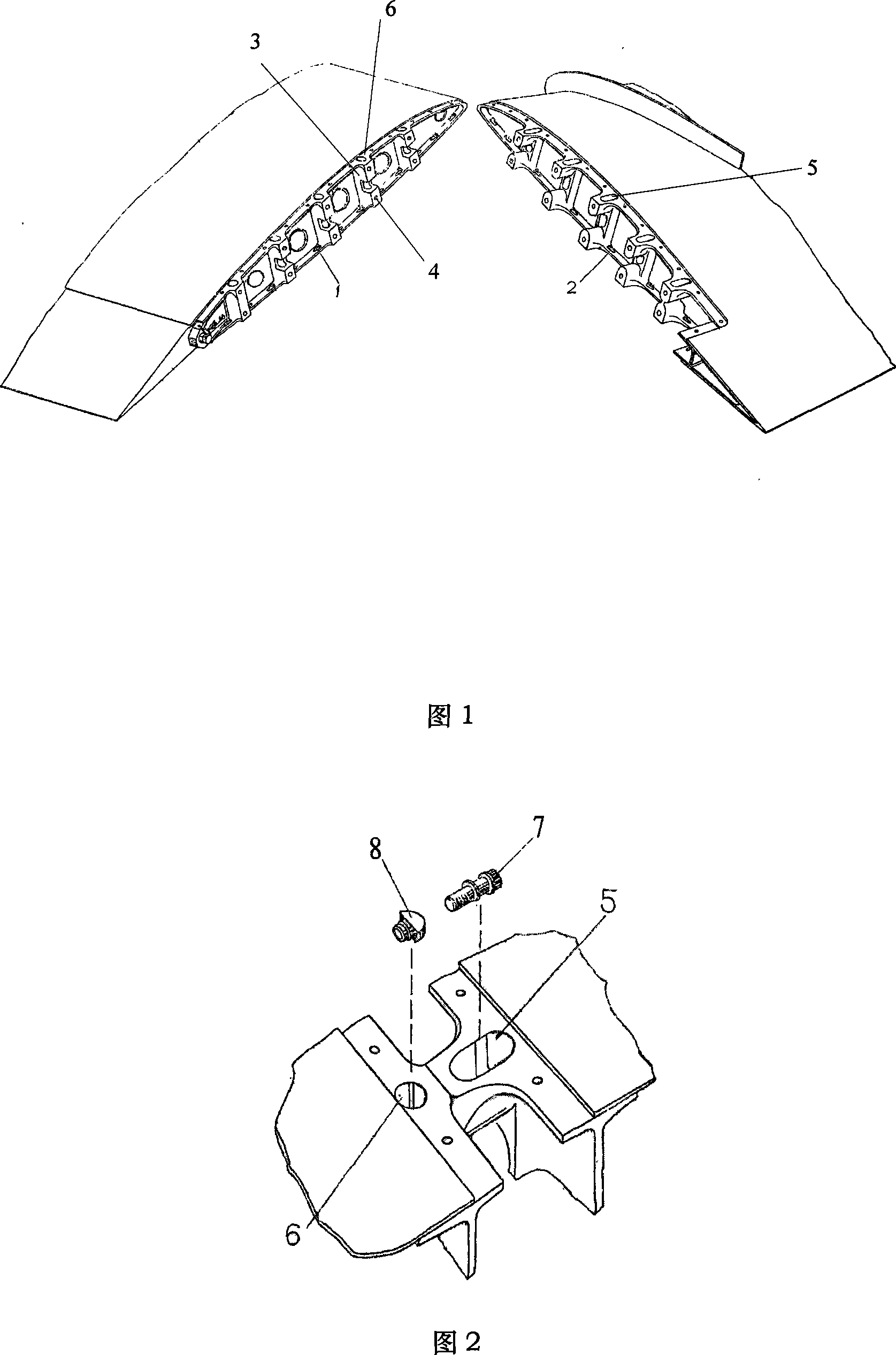
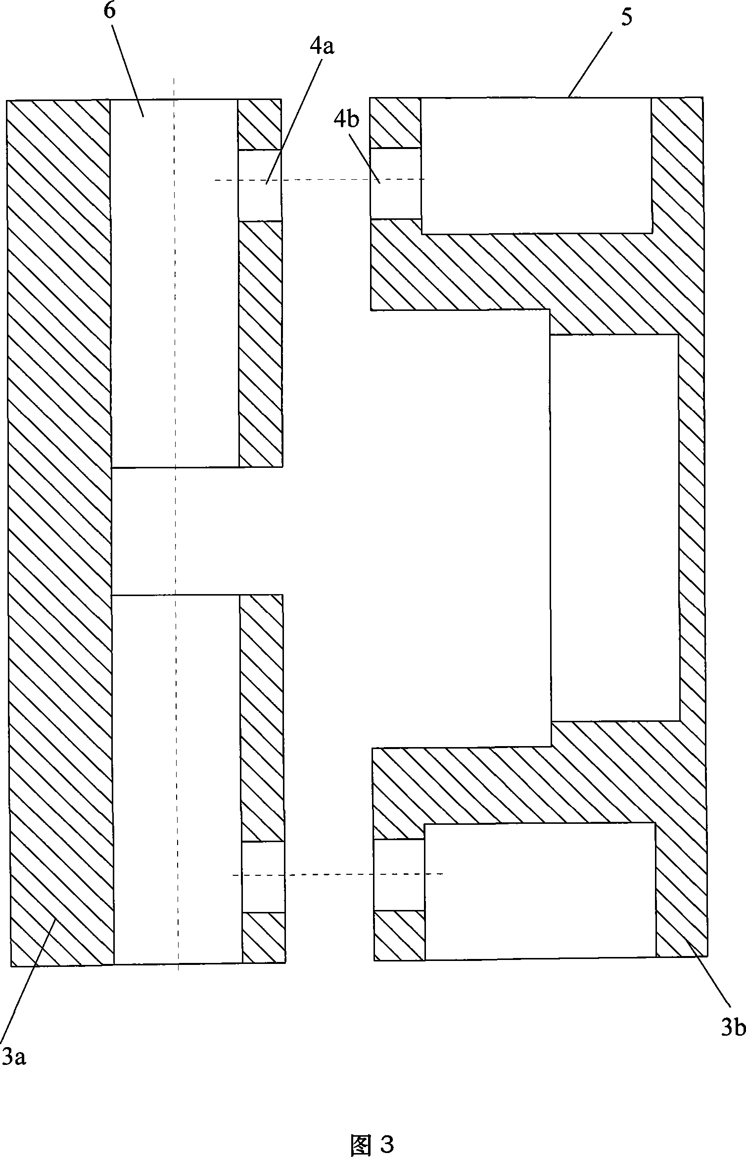
[0020] A connection structure of the middle and outer wings of an unmanned aerial vehicle of the present invention, as shown in Figure 1, the middle wing end rib 1 and the outer wing root rib 2 are aluminum alloy material reinforcement ribs with comb joints 3a, 3b, and the two reinforcement ribs At the butt joint, the middle wing and the outer wing are connected together by butt bolts 7 of high-strength aluminum alloy material. When docking, first align the comb-shaped joint connection holes of the center wing end rib 1 and the outer wing root rib 2 in sequence, as shown in Figure 2, place the butt bolt 7 horizontally into a bolt on the outer wing root rib 2 In the groove 5, place the arc-shaped supporting plate nut 8 horizontally into a corresponding nut placement groove 6 on the center wing end rib 1, and pass the butt bolts 7 throu...


PUM


Abstract

The present invention discloses a mid-wing and external-wing connection structure of an unmanned aerial vehicle. A mid-wing end rib and an external-wing root rib are the aluminium alloy reinforced ribs with comb-shaped joints. At the butt joint of the two reinforced ribs, the mid-wing and the external-wing are jointed by butt joint bolts made from high-intensified aluminium alloy material. After the mid-wing and the external-wing are butted, a joint seam is covered by a cowling made from composite material that is two rows of bolts are used fix the cowling at the reinforced ribs along the edge of the cowling. The mid-wing end rib and the external-wing root rib are considered as the butt joint of the mid-wing and the external-wing to integrate the joint and the structure as a whole, which reduces the complexity of the coordination relation and the connection relation and the manufacture error and assembly error by single joint, and the joint point and the grinder and the supporting structure of the external-wing are in one axial line, which ensures that the transmission force is continuous. The present invention has simple connection manner, which is convenient for disassembling and assembling and for checking the damage condition of a connection piece.

Description

technical field [0001] The invention belongs to the field of aviation machinery and relates to a technology for connecting the middle and outer wings of an unmanned aerial vehicle. Background technique [0002] At present, UAVs have been widely used in many fields such as campaign and strategic reconnaissance, surveillance, target positioning, target damage assessment, electronic countermeasures, and communication relay. Due to the advantages of UAVs such as low cost, good penetration capabilities and their outstanding performance in practice, the troops also urgently need to use various UAVs with excellent performance. Therefore, safety, reliability, economy and use requirements are the biggest challenges for UAV design. [0003] The task of the wing in flight is to generate lift to support the weight of the aircraft and to achieve maneuvering. At this time, huge aerodynamic forces act on the surface of the wing, and sometimes it is necessary to install engines, landing g...

Claims


Application Information

Patent Timeline
IPC IPC(8): B64C3/00A63H27/18
Inventor 李大伟范曼华李仪郭伟
Owner BEIHANG UNIV
Learn More