
Conversion adapter clamping structure

A joint clamping and adapter technology, which is applied in the direction of manufacturing tools, rigid shaft couplings, wrench, etc., can solve the problems of difficult positioning of magnetic bodies and adapters, small applicability, and difficulty

Inactive Publication Date: 2010-04-14
陈泰佐
View PDF5 Cites 0 Cited by
  • Summary
  • Abstract
  • Description
  • Claims
  • Application Information

AI Technical Summary

Problems solved by technology

[0003] 1. The positioning of the magnetic body and the adapter is not easy: the magnetic body is generally a disc-shaped magnet structure. The magnetic body is brittle and not easy to fix. The combination of the magnetic body and the adapter is mostly made of viscose, which is extremely wet Degumming is easy to occur, and during the fixing process of the viscose, the magnetic body and the adapter must be cleaned. If there is a slight uncleanness or oil film, the magnetic body cannot be fixed on the adapter, and it is easy to be improperly fixed. Detachment, and can not effectively make the adapter and tool clamp combined, so it is necessary to improve
[0004] 2. The positioning effect is not good: since the magnetic body is used for the function of positioning the inner diameter of the tool head by the effect of magnetic attraction, if the positioning is in a place with magnetic interference or when the magnetization is lost, it is difficult to have the effect of magnetic attraction. Or when the inner diameter of the tool head is made of non-magnetic or magnetically sensitive material, it cannot be applied, the applicability is extremely small, and the functionality is very limited, so there is a need for improvement

Method used


Image

  • Conversion adapter clamping structure
  • Conversion adapter clamping structure
  • Conversion adapter clamping structure

Examples


Embodiment Construction

[0029] In order to further understand the structure, characteristics and other purposes of the present invention, the following preferred embodiments are attached with drawings for detailed description as follows, but the embodiments described in this illustration are for illustration purposes, not for patent application. the only limitation.

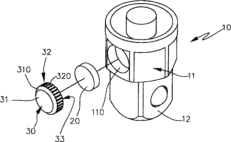
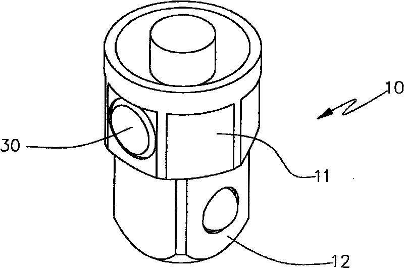
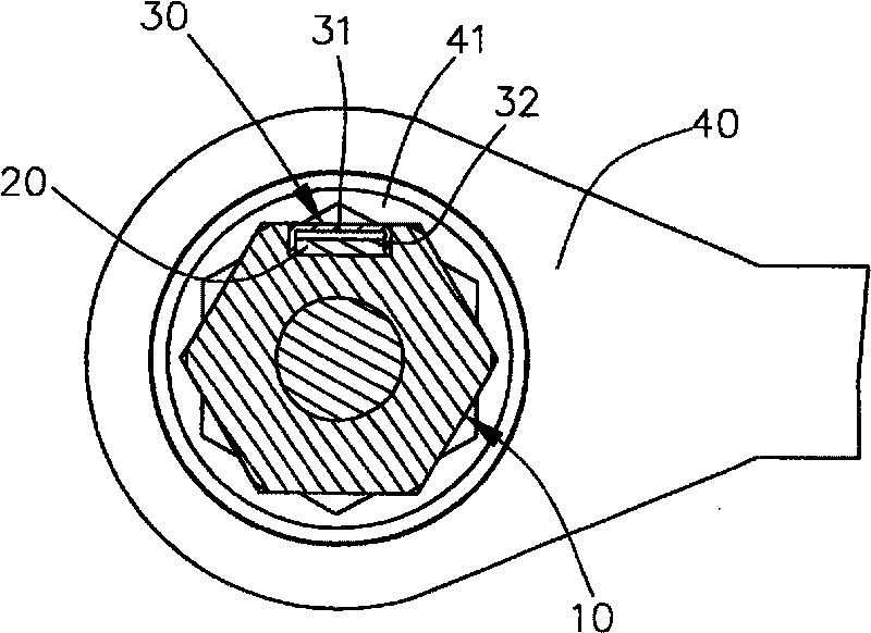
[0030] Please refer to Figure 1-Figure 4b As shown, the adapter 10 of the present invention is a general hexagonal to four-corner adapter structure, and it has a hexagonal large-diameter positioning part 11, and the positioning part 11 is provided with a groove-shaped fixing part 110, which can be used for magnetic materials. 20 is disposed therein, and one end of the adapter 10 protrudes from the detent portion 12 of the square column to detent the work or the sleeve.

[0031] And the fixing part 110 of the adapter 10 is provided with an elastic urging part 30 in addition. The clamping part 31, and the guide part 310 with a slope ex...


PUM


Abstract

The invention discloses an adapter clipping structure. An elastic fastening part is arranged on the clipping surface of an adapter and a tool head. The elastic fastening part is arranged in the fixingpart of the adapter so that the clipping part of the fastening part slightly protrudes beyond the surface of the adapter. When the adapter is arranged in the driving part of the tool head, the slightly protruding clipping part and the driving part produce clipping and fixing force in the form of elastic clipping so that the adapter can be fixed at the inside diameter position of the driving partofthe tool head. The elastic fastening force of the fixed part of the fastening part protruding in the fixing part is used so that a magnetic body inside the fastening part and the fastening part canbe fixed in the fixing part without damaging the magnetic body, thus achieving high stability, more reliable elastic clipping force and more reliable combination of the fastening part.

Description

Technical field: [0001] The invention relates to a clamping structure of an adapter, in particular to a clamping structure of an adapter suitable for hand tools or pneumatic tools. The control part protrudes slightly from the surface of the adapter, and when it is clamped with the driving part of the tool head, it will deform elastically, and the fixing part of the pressing part will extend into the fixing part of the adapter, and be elastically fixed to achieve high safety and high performance. purpose of stability. Background technique: [0002] At present, the clamping or positioning structure of the adapter and the tool, such as the new patent of Taiwan No. 90202459 "Magnetic Wrench Jaw Changing Device", although its structural features are aimed at the wrench tool. Open jaws or sleeve-hole jaws are used as different types of jaw conversion parts. Through the use of jaw conversion parts, it is suitable for locking and unloading operations of bolts (caps) of other specif...

Claims


Application Information

Patent Timeline
Patent Type & Authority Patents(China)
IPC IPC(8): F16D1/02B25B23/00
Inventor 陈泰佐
Owner 陈泰佐
Learn More