Electric power steering device
An electric power steering, electric motor technology, applied in the direction of electric steering mechanism, etc., can solve the problems of influence, position accuracy deviation, inability to assemble, etc.
- Summary
- Abstract
- Description
- Claims
- Application Information
AI Technical Summary
Problems solved by technology
Method used
Image
Examples
no. 1 approach
[0041] Next, a first embodiment of the present invention will be described.
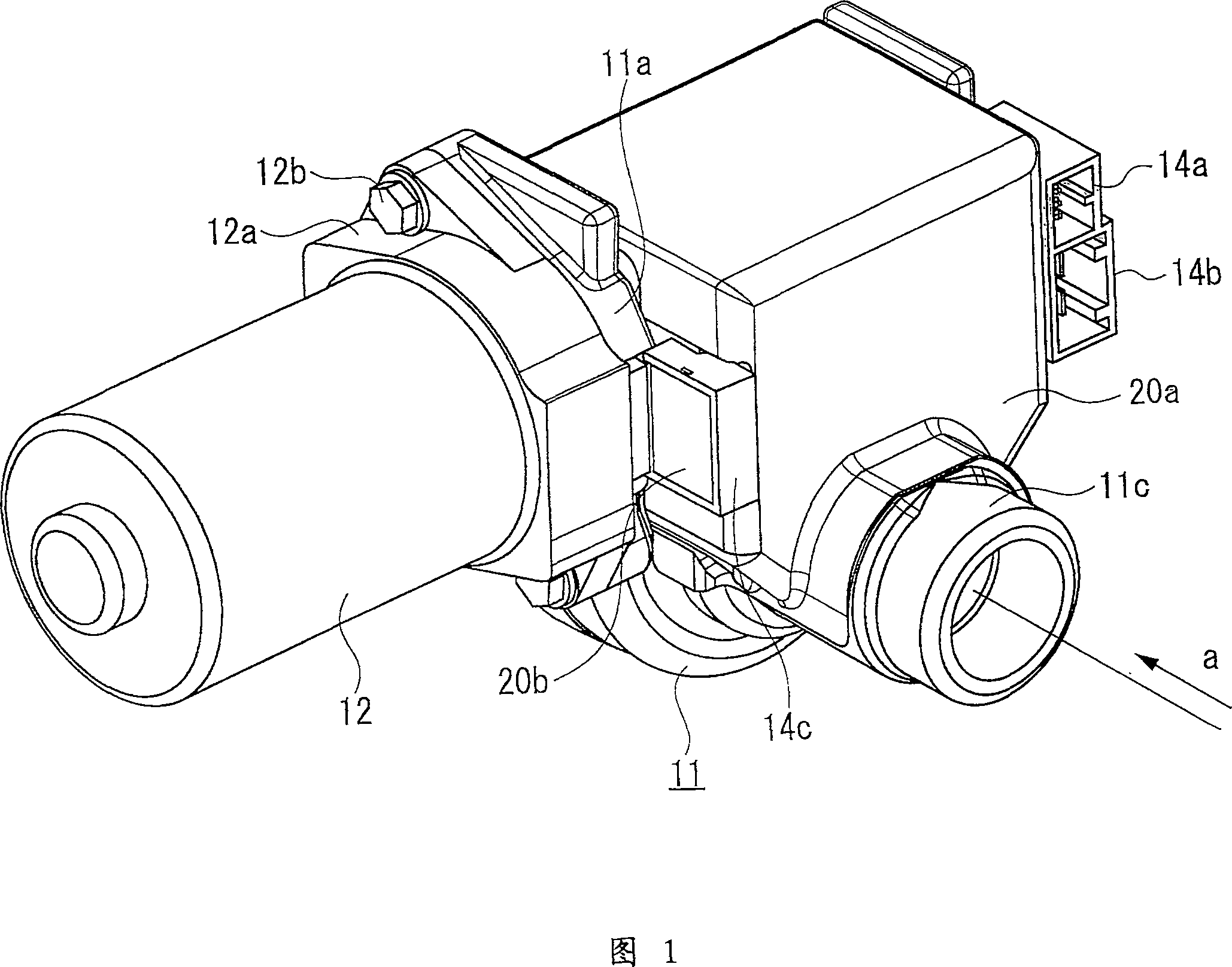
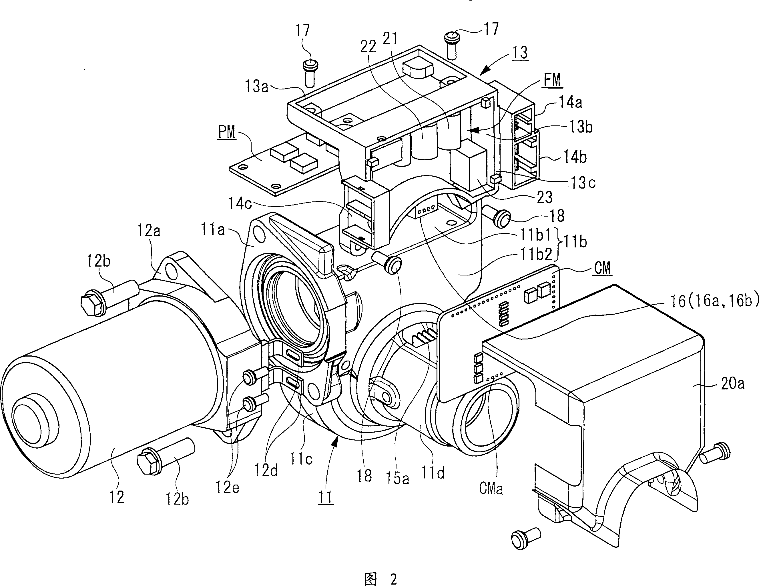
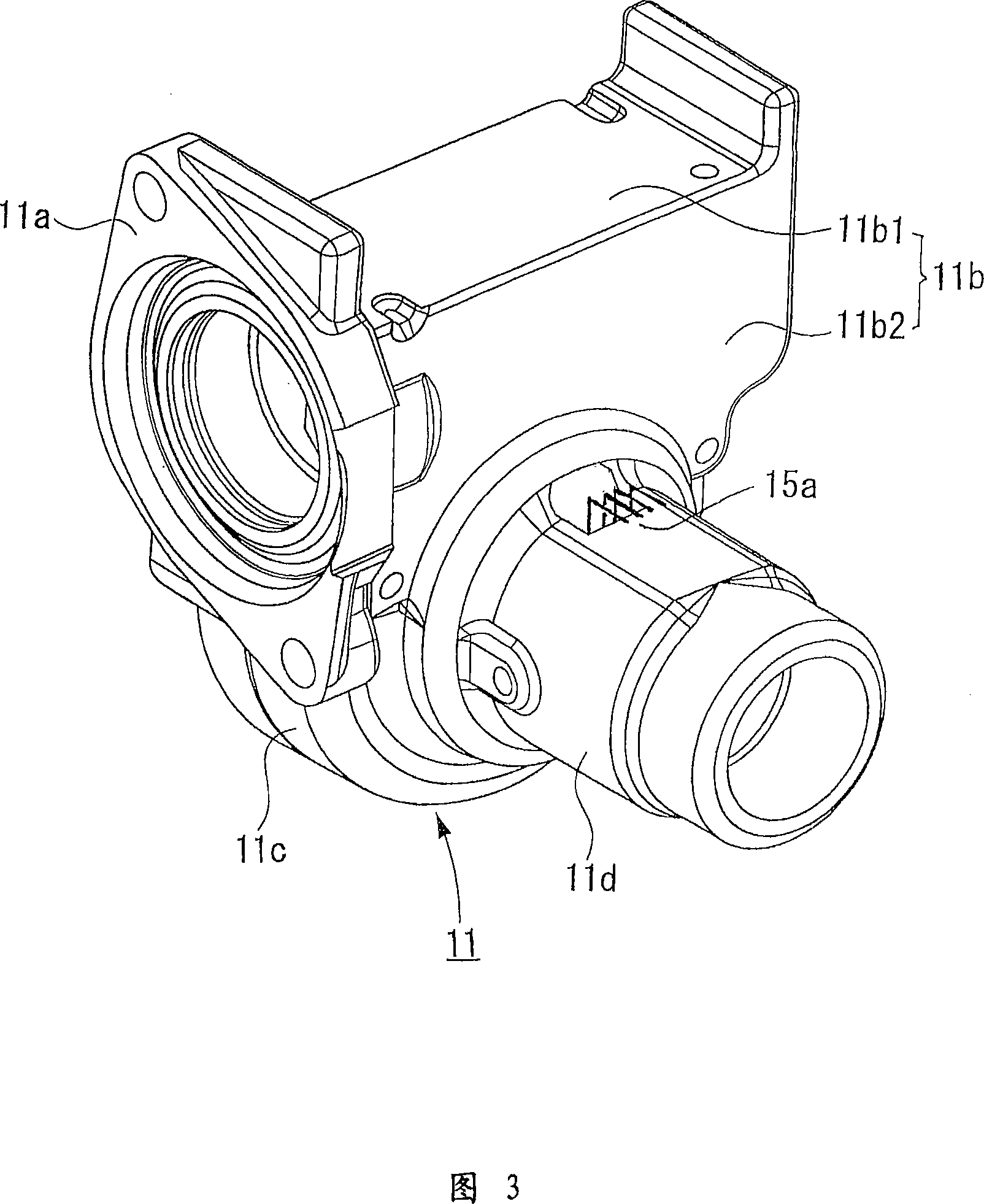
[0042] 1 is an external view of the main components of the electric power steering system according to the first embodiment, FIG. 2 is an exploded perspective view of the main components, FIG. 3 is a perspective view illustrating the shape of a gear box, and FIG. 5 is a perspective view illustrating a state in which the motor and covers are removed from the structure shown in FIG. 1 . In addition, in order to avoid complicating the drawing, illustrations of the steering shaft, the input shaft, the output shaft, and the reduction gear connected thereto are omitted.
[0043] In Fig. 1 to Fig. 5, 11 is the gearbox of the steering device, and 12 is the electric motor. Although not shown, inside the gearbox 11, a cylindrical input shaft connected to the steering shaft, a torsion bar coaxially arranged inside it, and a torsion bar connected to the torsion bar and coaxially arranged with the input shaft T...
no. 2 approach
[0082] Next, an electric power steering system according to a second embodiment of the present invention will be described. The electric power steering system of the second embodiment is different from the electric power steering system of the first embodiment except for the shapes of the gear box and the module mounting parts of the first embodiment, and other structural components are not changed. The same structural components of the electric power steering device are marked with the same symbols and their descriptions are omitted, and only the differences are described.
[0083] FIG. 10 is a diagram illustrating an outline of a gear case 25 and a module mounting member 26 of an electric power steering system according to a second embodiment, which is similar to FIG. 17(a) and FIG. 17(b) described in the subject to be solved by the present invention. It is easy to understand the structure by comparison. 10( a ) shows the state before mounting of the module mounting member ...
no. 3 approach
[0095] Next, an electric power steering system according to a third embodiment of the present invention will be described. FIG. 15 is a diagram illustrating an outline of a gear box 31 and a module mounting member 33 of an electric power steering system according to a second embodiment, which is similar to FIG. 17(a) and FIG. 17(b) described in the subject to be solved by the present invention. It is easy to understand the structure by comparison. 15( a ) shows the state before mounting of the module mounting member 13 , and FIG. 15( b ) shows the state after mounting.
[0096] In the gear case 31 of the third embodiment, the first plane 31b1 and the second plane 31b2 intersect each other substantially perpendicularly in an L-shape.
[0097] Furthermore, the output terminal of the torque sensor 15 is on a plane including the above-mentioned input shaft, and the front end portion of the output terminal is arranged obliquely in a direction away from the input shaft.
[0098] O...
PUM
 Abstract
Description
Claims
Application Information
 - R&D
- Intellectual Property
- Life Sciences
- Materials
- Tech Scout
- Unparalleled Data Quality
- Higher Quality Content
- 60% Fewer Hallucinations
Browse by: Latest US Patents, China's latest patents, Technical Efficacy Thesaurus, Application Domain, Technology Topic, Popular Technical Reports.
© 2025 PatSnap. All rights reserved.Legal|Privacy policy|Modern Slavery Act Transparency Statement|Sitemap|About US| Contact US: help@patsnap.com


