Suction cup type knife sharpener

A knife sharpener and sucker-type technology, which is applied in grinding/polishing equipment, grinding/polishing hand tools, metal processing equipment, etc., can solve the problems of inability to position, inability to grind the blade, inconvenient use, etc., and achieve the goal of using Safe and convenient, good grinding effect, easy to store

Inactive Publication Date: 2011-01-26
陈增平
View PDF6 Cites 0 Cited by
  • Summary
  • Abstract
  • Description
  • Claims
  • Application Information

AI Technical Summary

Problems solved by technology

[0002] Traditional sharpening stones, sharpening steel rods or rolling grinding wheels are often used for sharpening knives, which is inconvenient to use; the 'quick sharpener' disclosed in Chinese patent 96239439.4 consists of two superimposed sharpening blades intersecting two sharp edges The sides form a double-sided V-shaped sharpening notch; when sharpening the knife, the edge to be ground is placed on the V-shaped notch, the blade is pulled, and the sharp edges on both sides of the V-shaped notch cut the two sides of the sharpened blade. Generate new sharp blades to achieve the purpose of sharpening
Its disadvantages: First, when the blade to be ground is placed in the V-shaped notch, there are three degrees of freedom of rotation relative to the V-shaped notch, that is, the blade to be ground can rotate in all directions relative to the V-shaped notch It cannot be positioned, it is difficult to ensure straight-line grinding, and the quality of the ground blade is not good; the second is that when using this knife sharpener for knife sharpening operation, it is necessary to hold the knife sharpener in one hand and the knife in the other. The blade is potentially harmful to the hand holding the sharpener and is not safe
The third is that this double-sided V-shaped sharpening notch cannot grind a blade with teeth on one side and teeth on the other side, such as a steak knife.

Method used


Image

  • Suction cup type knife sharpener
  • Suction cup type knife sharpener
  • Suction cup type knife sharpener

Examples


Embodiment Construction

[0021] The present invention will be further described below in conjunction with the accompanying drawings and embodiments.

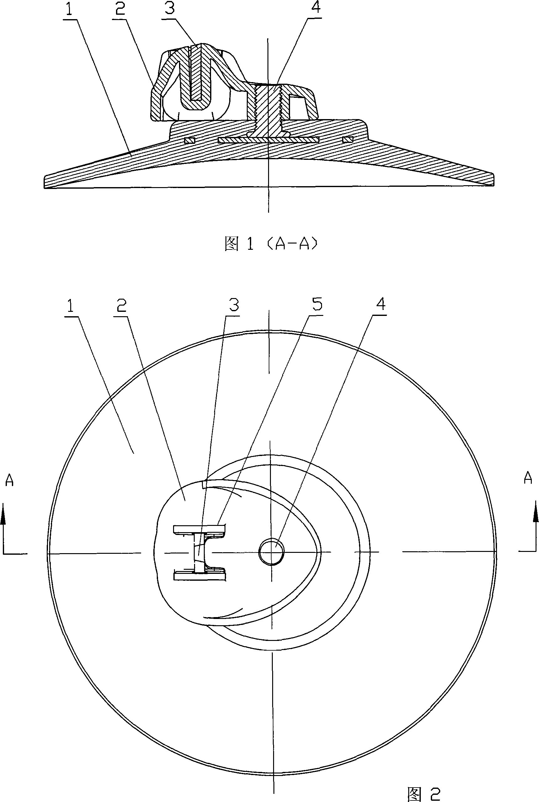
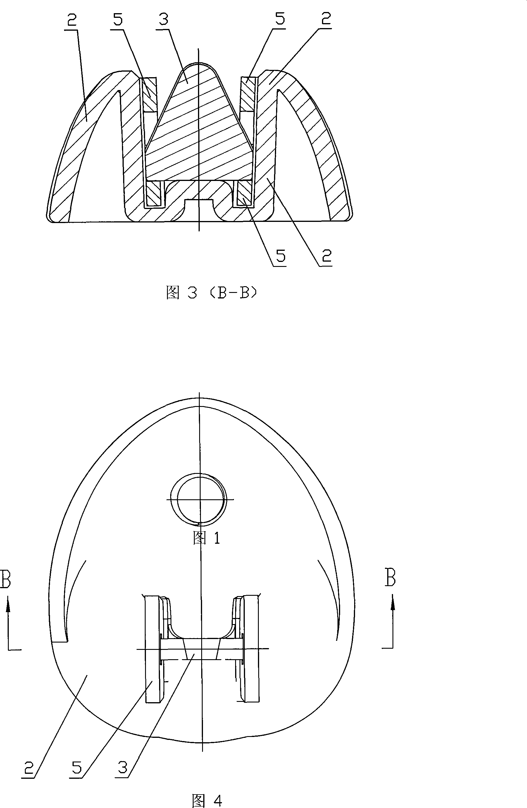
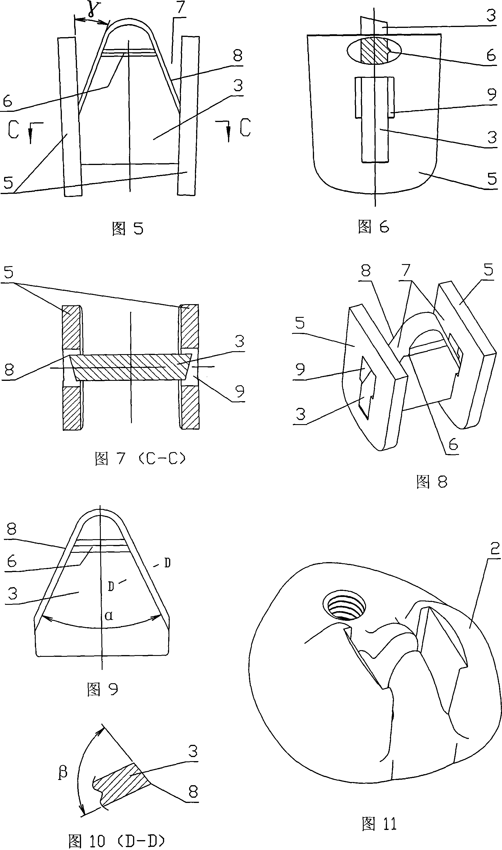
[0022] An example of an embodiment is shown in Figure 1-11: a suction cup sharpener, its bolt 4 is pre-embedded in a soft plastic suction cup 1 and is tightly connected with it as a whole, the screw hole of the support 2 is screwed with the bolt 4, Fasten the support 2 on the suction cup 1. Two rectangular linings 5 ​​with rounded corners are placed in the groove of the support 2 in an inverted splayed shape. The center of the lining 5 is provided with a rectangular hole 9, and the two sides of the lower part of the single carbide grinding blade 3 are positioned and inserted in In the oblong holes 9 of the left and right linings 5, the whole is packed into the groove of the support 2. Carbide grinding blade 3 is an isosceles triangular thin-shaped frustum with rounded corners, and the large isosceles triangular surface of the truncated cone is a smooth...


PUM


Abstract

The invention relates to a sucker-typed cutter grinder. Bolts of the cutter grinder are fixedly and tightly integrated with a sucker and a support base is arranged on the sucker through bolts; two rectangle pads with round angles are positioned in a V shape in a groove of the support base and the center of the pad is provided with a rectangle hole; the two sides of the lower part of a single grinding disc are inserted to the rectangle holes on the right pad and the left pad for locating. The grinding disc is a thin isosceles frustum with round angles; the two sides of the large isosceles triangle of the frustum are provided with sharp edges and projected edges are arranged at the upper part of the small isosceles triangle of the frustum; the sharp edges and the surface of the V-shaped pads form a right single-face V-shaped grinding notch and a left single-face V-shaped grinding notch. The invention has small size, light weight and is easy to store, thus being in particular suitable for household application; the cutter grinder is fixed to a smooth counter through a sucker and a cutter can be grinded with one hand on the two single-face grinding notches and the grinding is safe andconvenient with good effect and wide application; the cutter grinder is also suitable for the cutter with teeth at one side and no teeth at the other side.

Description

technical field [0001] The invention relates to a tool for sharpening a knife edge, in particular to a suction cup type knife sharpener. Background technique [0002] Traditional sharpening stones, sharpening steel rods or rolling grinding wheels are often used for sharpening knives, which is inconvenient to use; the 'quick sharpener' disclosed in Chinese patent 96239439.4 consists of two superimposed sharpening blades intersecting two sharp edges The sides form a double-sided V-shaped sharpening notch; when sharpening the knife, the edge to be ground is placed on the V-shaped notch, the blade is pulled, and the sharp edges on both sides of the V-shaped notch cut the two sides of the sharpened blade. Generate new sharp blades to achieve the purpose of sharpening. Its disadvantages: First, when the blade to be ground is placed in the V-shaped notch, there are three degrees of freedom of rotation relative to the V-shaped notch, that is, the blade to be ground can rotate in al...

Claims


Application Information

Patent Timeline
Patent Type & Authority Patents(China)
IPC IPC(8): B24D15/02B24D15/06
Inventor 陈增平
Owner 陈增平
Why Eureka
Try Eureka