Radiating machine of vehicle

A technology for automobiles and exhaust fans, which is applied to vehicle components, heating/cooling equipment, air handling equipment, etc., can solve the problems of inconvenience, time-consuming and laborious removal of coverings, and large space occupation, and achieves easy fixed installation, design and Flexible installation and simple structure

Inactive Publication Date: 2008-07-16
黄进发
View PDF0 Cites 0 Cited by
  • Summary
  • Abstract
  • Description
  • Claims
  • Application Information

AI Technical Summary

Problems solved by technology

The disadvantage of this method of parking is that it takes time and effort to set up the cover and remove the cover before driving, and the space occupied by carrying the cover in the vehicle is often relatively large, which is not convenient enough

Method used


Image

  • Radiating machine of vehicle
  • Radiating machine of vehicle
  • Radiating machine of vehicle

Examples


Embodiment 1

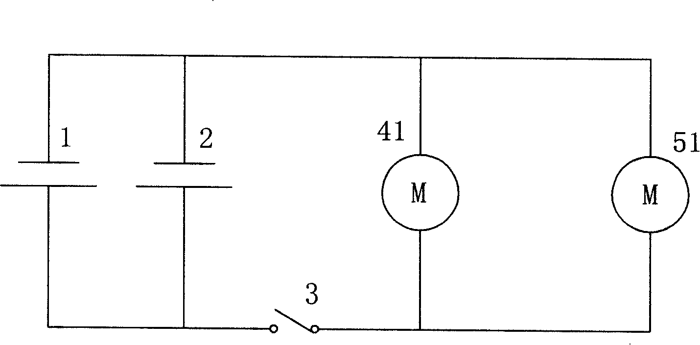
[0017] The circuit structure of an embodiment of the automobile radiator of the present invention, as figure 1 shown. A solar panel 1 and a storage battery 2 are arranged in the power supply unit of the car radiator. The solar panel 1 and the storage battery 2 are connected in parallel with each other. The motors 41 and 50 of the two electric exhaust fans 4 and 5 are connected in parallel, and one of their power input terminals is connected to the negative pole of the power supply device; the other power input terminal is connected to the positive pole of the power supply device through a switch 3 to form a closed series circuit.

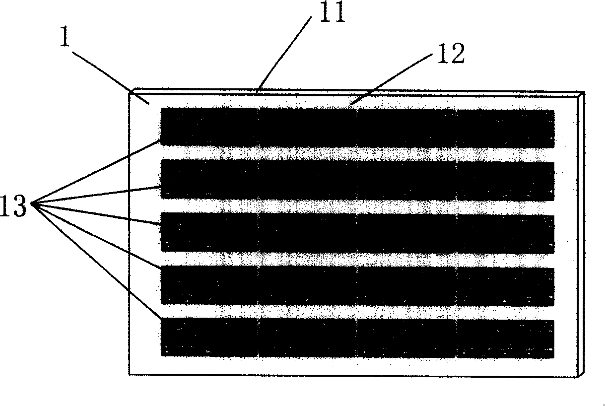
[0018] In the present embodiment, the structure of the solar battery panel 1 is as follows figure 2 shown. A bottom plate 12 made of insulating material is arranged inside the frame 11 , and a plurality of solar cells 13 are fixed in an array on the upper surface of the bottom plate 12 . The solar cells 13 are connected in series in columns and...

Embodiment 2

[0023] Two exhaust fans 4', 5' of the second embodiment of the automobile radiator of the present invention adopt axial flow exhaust fans. In the circuit structure of the present embodiment, replace the motors 41, 51 of the two exhaust fans 4, 5 in the circuit structure of the previous embodiment with the motors 41 ′, 51 ′ of two exhaust fans 4 ′, 5 ′, and the other parts are identical. So no more details.

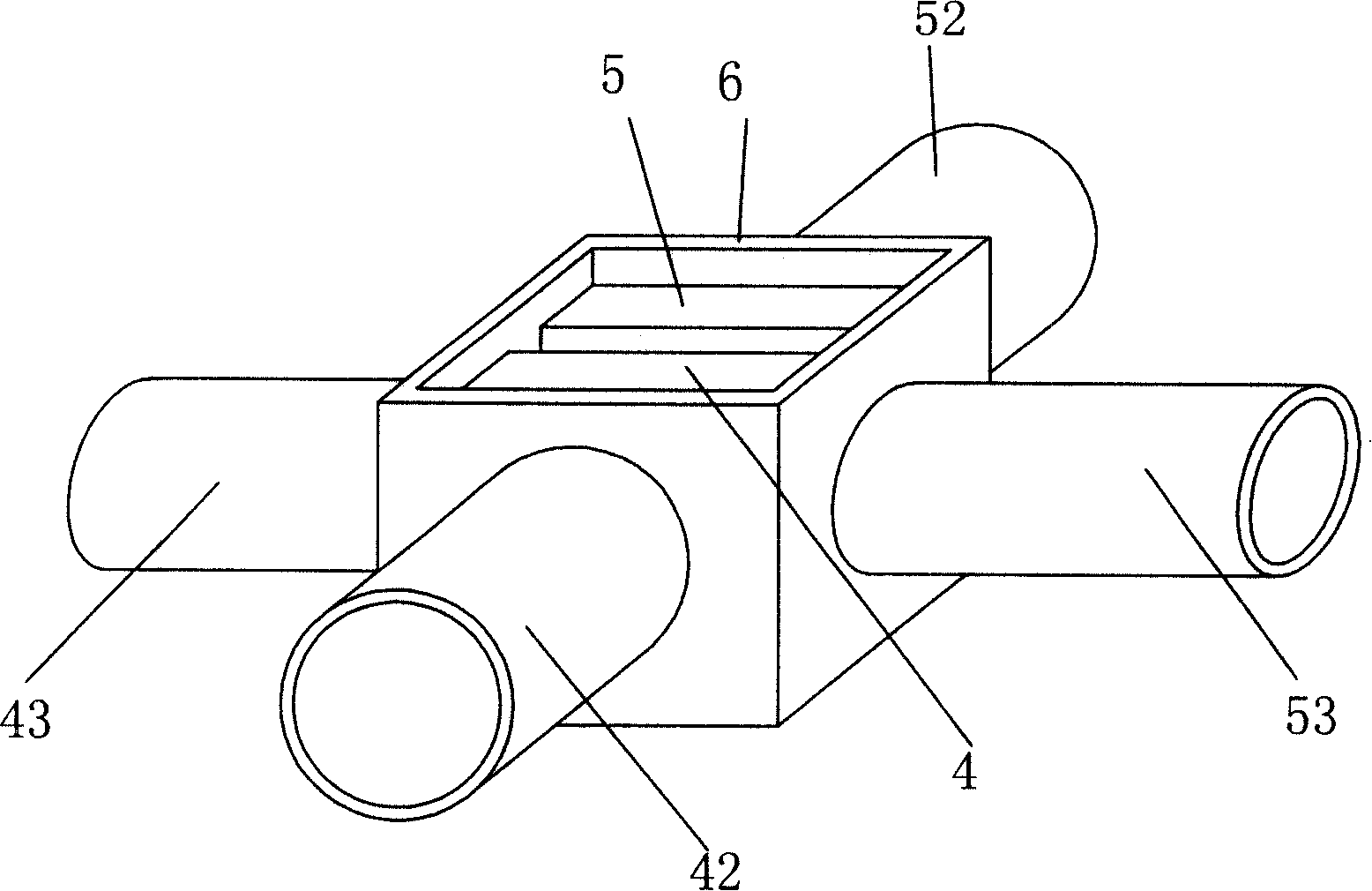
[0024] The motors 41', 51' of the two exhaust fans 4', 5' of this embodiment are fixed side by side in a housing 6' in reverse, forming an independent air supply and exhaust device, such as Figure 5 shown. In the air supply and exhaust device of the present embodiment, the air inlet nozzle 42' of the exhaust fan 4' and the outlet nozzle 53' of the exhaust fan 5' are drawn outward from the left side of the housing 6', and the exhaust fan 4' The air outlet pipe port 43' and the air inlet pipe port 52' of the exhaust fan 5' are drawn out from the right side of the casing 6...


PUM


Abstract

The invention discloses an automobile radiator, relating to a device which keeps temperature inside a carriage of the automobile close to outside temperature. The invention solves the problem of fuel consumption and inconvenient utilization. The invention has a power device which supplies electricity for motors of two electric exhaust blowers through a switch, and the two electric exhaust blowers are equipped inside the automobile; the first exhaust blower of the two exhaust blowers feeds air outside the automobile into the carriage, and the second one exhausts the air inside the carriage out of the carriage. The invention can feed air with relatively low temperature air outside the automobile into the carriage and then exhaust relatively high temperature air inside the carriage out of the carriage, and thus forming air circulation flow inside the carriage and bringing away the heat inside the carriage. The steward can operate the exhaust blowers by dialing a switch to radiate the relatively high temperature inside the carriage out of the carriage through air exchanging and keep the temperature inside the carriage the same with the temperature outside the carriage. When driving is desired, the steward can enter the carriage in time to drive the automobile. The invention is quite convenient in utilization and simple in structure.

Description

technical field [0001] The invention relates to a device for keeping the temperature in the compartment of an automobile close to that of the outside. Background technique [0002] For a vehicle parked in the outdoor sunlight, since the doors and windows are closed, the air temperature in the compartment will gradually increase due to the increase in the temperature of the vehicle body. In summer, the temperature inside the car may even exceed the atmospheric temperature outside the car by 10°C-20°C. Passengers will feel unbearable to enter the compartment. For avoiding this puzzlement, existing solution mode has two classes: the one, start air-conditioning refrigeration equipment, inject cold air in the compartment, forcibly reduce the temperature of air in the compartment. The disadvantage of this method is that it needs to consume extra fuel and wait for a while. Although the temperature of the air in the car has dropped, the surface temperature of the seats and other ...

Claims


Application Information

Patent Timeline
Patent Type & Authority Applications(China)
IPC IPC(8): B60H1/24
Inventor 黄进发
Owner 黄进发
Why Eureka
Try Eureka