A simulation test system for the whole process of dynamic evolution of dam-break debris flow

A simulation test system and debris flow technology, applied in teaching models, soil material testing, material inspection products, etc., can solve the problems of not being able to meet the requirements of high-speed camera light sources, the difficulty of locking the baffle, and the sharp increase in weight, etc., to achieve The effect of preventing irreversible damage, simple assembly, and strong simulation ability

Active Publication Date: 2021-10-08
TONGJI UNIV
View PDF17 Cites 0 Cited by
  • Summary
  • Abstract
  • Description
  • Claims
  • Application Information

AI Technical Summary

Problems solved by technology

[0005] (1) In a supergravity environment, the lateral earth pressure of the fill in the storage box on the baffle is dozens of times higher than that under 1g of gravity. Under the huge lateral pressure, how to ensure that the baffle is closed in the initial state The locked state is the first major technical difficulty of this type of test system, and with the increase of the simulation volume, the difficulty of realizing the locked baffle will be further greatly increased;
[0006] (2) The weight of the baffle itself also increases sharply with the increase of centrifugal acceleration, resulting in an increase in its inertia. Therefore, how to increase the opening speed of the baffle under the supergravity field is the second major technical difficulty of this type of test system;
[0008] (4) The centrifuge room is a closed environment, so how to remotely control the opening of the baffle to simulate the whole process of debris flow is the fourth major technical difficulty of this type of test system;
[0009] (5) Common light sources are mostly used in the centrifuge room. This light source is sufficient for conventional lighting, but it cannot meet the requirements of high-speed cameras for light sources. Therefore, how to artificially supplement the light during the high-speed camera process is a test of this type. The fifth major technical difficulty of the system

Method used


Image

  • A simulation test system for the whole process of dynamic evolution of dam-break debris flow
  • A simulation test system for the whole process of dynamic evolution of dam-break debris flow
  • A simulation test system for the whole process of dynamic evolution of dam-break debris flow

Examples


Embodiment

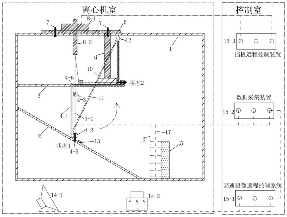
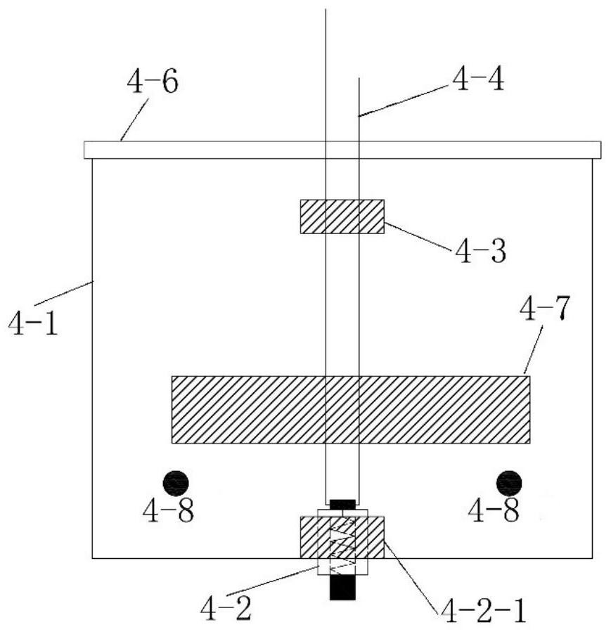
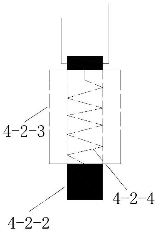
[0042] like figure 1 As shown, this application proposes a simulation test system for the whole process of dynamic evolution of dam-break debris flow, which is suitable for the high-gravity centrifugal test platform, including: a model box 1, which is located in the centrifuge room, and is used to simulate the start-up, movement, impact and impact of debris flow. The whole process of dynamic evolution of stacking includes the storage box 3, the baffle plate 4, the sliding surface 2, the blocking structure 5, and the motor 8. The plate 4 is rotatably arranged at the outlet of the material storage box 3 toward the bottom of the sliding surface 2, and the motor 8 controls the opening of the baffle plate 4; the data acquisition system includes the sensor arranged in the model box 1, and the data acquisition system connected with the sensor Device 15-2, data acquisition device 15-2 is arranged in the control room; High-speed camera system is located in the centrifuge room, includin...


PUM


Abstract

The invention relates to a simulation test system for the whole process of dynamic evolution of dam-break debris flow, comprising: a model box, which is installed in the centrifuge chamber, for simulating the entire process of dynamic evolution of debris flow, including a storage box, a baffle plate, a sliding surface, and a barrier Structure and motor, the storage box and the blocking structure are respectively arranged on the upper part and the front side of the bottom of the sliding surface, and the baffle is rotatably arranged at the outlet of the storage box toward the bottom of the sliding surface, and the motor controls the baffle The opening of the centrifuge; the data acquisition system includes sensors installed in the model box; the high-speed camera system is installed in the centrifuge room, including a high-speed camera and a bright LED light source. Compared with the prior art, the present invention has the advantages of strong simulation ability, can truly reproduce the whole process of debris flow dynamic evolution, full automation, remote control, easy to use, and low economic cost.

Description

technical field [0001] The invention relates to the field of engineering geology, in particular to a simulation test system for the whole process of dynamic evolution of dam-break debris flow. Background technique [0002] In recent years, geological disasters of large deformation and flow of soil such as debris flows have caused great economic property losses and casualties because of their huge impact damage effects and unpredictable characteristics. At present, the disaster-causing mechanism of this kind of geological disaster has not been completely resolved, mainly reflected in the unclear dynamic evolution mechanism of the debris flow initiation, movement, impact and accumulation process. One of the difficulties in the above scientific research is the lack of scientific and effective physical simulation methods. [0003] At present, domestic and foreign researches mostly use conventional gravity model tests to carry out the dynamic evolution process test of debris flow...

Claims


Application Information

Patent Timeline
Patent Type & Authority Patents(China)
IPC IPC(8): G01N33/24G09B23/40
CPCG01N33/24G09B23/40
Inventor 黄雨张贝
Owner TONGJI UNIV
Why Eureka
Try Eureka