Portrait multi-point continuously dragging construction method for trussed steel beam

A construction method and technology of steel truss girder, applied in the direction of bridges, bridge construction, erection/assembly of bridges, etc., can solve the problems of unsuitable use in strong wind areas, difficult temporary piers, and great environmental impact of temporary piers, so as to shorten the construction period, Safe production is beneficial and the effect of reducing high-altitude work

Active Publication Date: 2008-07-16
CHINA RAILWAY MAJOR BRIDGE ENG GRP CO LTD
View PDF0 Cites 35 Cited by
  • Summary
  • Abstract
  • Description
  • Claims
  • Application Information

AI Technical Summary

Problems solved by technology

Using this method to erect steel girders has the following three problems: (1) It requires a high suspension tower and is greatly affected by wind, so it is not suitable for use in strong wind areas
In addition, the assembly of the sling tower itself belongs to high-altitude operations, the assembly period is long, and it is not safe
(2) Since the sling tower needs to provide a large upward pulling force at the cantilever end of the steel beam, and needs to be symmetrically cable-stayed front and rear, the tower needs to bear double the vertical pressure, and the force is very large, while meeting the vertical height , In the case of rigidity requirements, the steel tower itself has strong requirements, the structure is very large, and the cost is high
This method has

Method used


Image

  • Portrait multi-point continuously dragging construction method for trussed steel beam
  • Portrait multi-point continuously dragging construction method for trussed steel beam
  • Portrait multi-point continuously dragging construction method for trussed steel beam

Examples


Embodiment 1

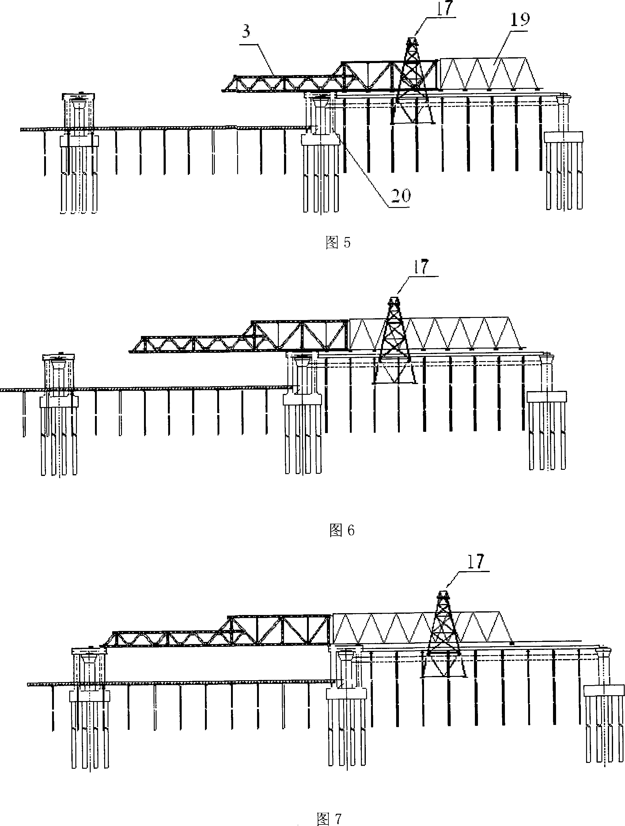
[0049] 1. Set up the construction platform support on the 7~8# pier, install the 108m guide beam 108m on the support, then drag the guide beam to the 0# pier direction and move forward for 48m, and assemble the 4 steel truss girders. See Figure 5

[0050] 2. Then drag 36m towards the direction of pier 0#, and continue to assemble 3 sections of the steel truss girder. See Figure 6

[0051] 3. Drag 30m in the direction of pier 0#, and the leading beam reaches the bracket next to pier 6#. See Figure 7

[0052] 4. Continue to drag 54m in the direction of pier 0#, and 7 internode positions are vacated on the scattered support. See Figure 8

[0053] 5. Assemble 7 internodes of steel truss beams on the steel beam assembly platform support.

[0054] 6. Drag 84m as a whole, and then assemble 7 steel truss girders on the steel girder assembly platform support. See Figure 9

[0055] 7. Repeat the above steps, and drag the steel truss beam to the 0# pier. (The guide beam can be di...


PUM


Abstract

The invention relates to a drag construction method of a steel truss girder, in particular to a steel truss girder multi-point continuous vertical drag construction method; wherein, a front guide beam is arranged in the front end of the steel truss girder, and a steel truss girder assembling construction platform bracket is arranged among bridge pier bodies; a whole internode is made by using the line-cross gate-hanging assembling steel beam bar, and then the multi-point synchronous continuous drag steel truss girder and the front guide beam are moved forward; the steel truss girder internode bar components are sequentially assembled on the vacate assembling bracket; the multi-point synchronous continuous drag steel truss girder continues to move forward to n internodes, and the erection of the steel truss girder is finished by recycling like that. The invention has the advantages of assembling the steel beam in bearings of a bank, having the ability of doing the industrialized work, avoiding the bad effect to the welding of the steel beam and the high strength bolt wring quality caused by the rain season and winter season, guaranteeing the quality, and shortening the construction time efficiently.

Description

technical field [0001] The invention relates to a dragging construction method of a steel truss girder, in particular to a multi-point continuous longitudinal dragging construction method of a steel truss girder. Background technique [0002] With the rapid development of my country's economy and technology, more and more steel girder bridges need to be built. Steel girder bridges with large spans and multi-span continuous (or temporary continuous and then simply supported) are often used when crossing large rivers. The erection of steel truss girders is generally carried out by loose assembly, the construction period is long, and the welding quality of steel truss girders is not easy to guarantee in winter. Therefore, in order to improve the quality of erecting steel truss girders and shorten the construction period, construction workers generally assemble steel girders on shore supports as much as possible to achieve factory operations and avoid quality problems caused by...

Claims


Application Information

Patent Timeline
IPC IPC(8): E01D21/00
Inventor 秦顺全周外男宋杰姚发海毛伟琦李军堂涂满明姚森段志勇王东辉马涛张爱花周超舟
Owner CHINA RAILWAY MAJOR BRIDGE ENG GRP CO LTD
Why Eureka
Try Eureka