
Ethernet ring protection method, system and device

An Ethernet and node technology, applied in the field of ring network protection, can solve the problems of lack of link fault detection function, inability to realize fast protection switching, and the master node not being able to know the link status in time, so as to avoid loops.

Active Publication Date: 2008-07-16
NEW H3C TECH CO LTD
View PDF0 Cites 14 Cited by
  • Summary
  • Abstract
  • Description
  • Claims
  • Application Information

AI Technical Summary

Problems solved by technology

However, these relay devices are usually pure physical layer devices, only perform physical layer relay, do not have the function of link fault detection, and cannot report LINK_DOWN messages to the master node when the relay transmission link fails, resulting in The master node cannot know the link status in time, and cannot realize fast protection switching when the relay transmission link fails

Method used


Image

  • Ethernet ring protection method, system and device
  • Ethernet ring protection method, system and device

Examples


Embodiment Construction

[0028] In order to make the object, technical solution and advantages of the present invention clearer, the present invention will be further described in detail below with reference to the accompanying drawings and examples.

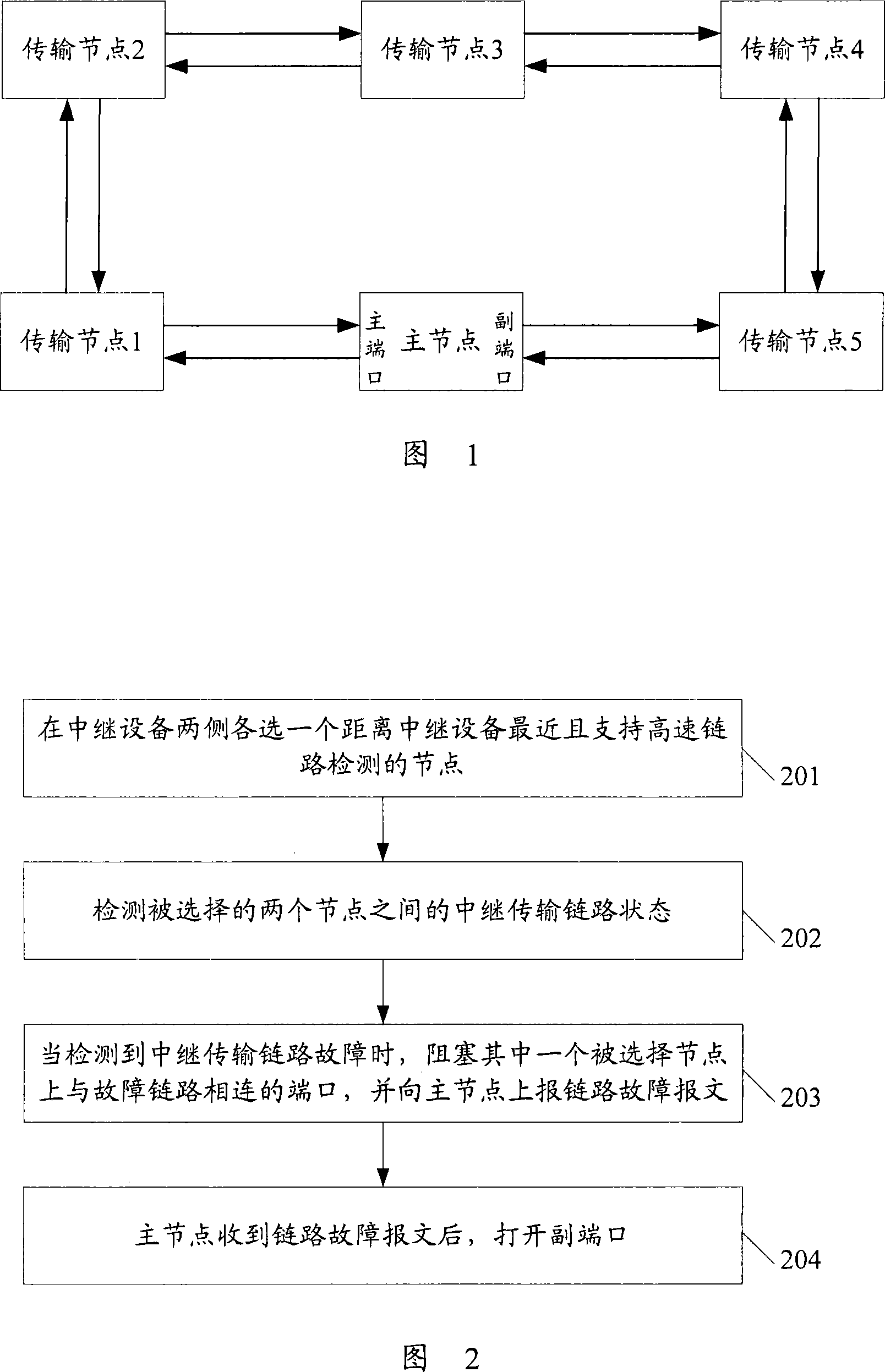
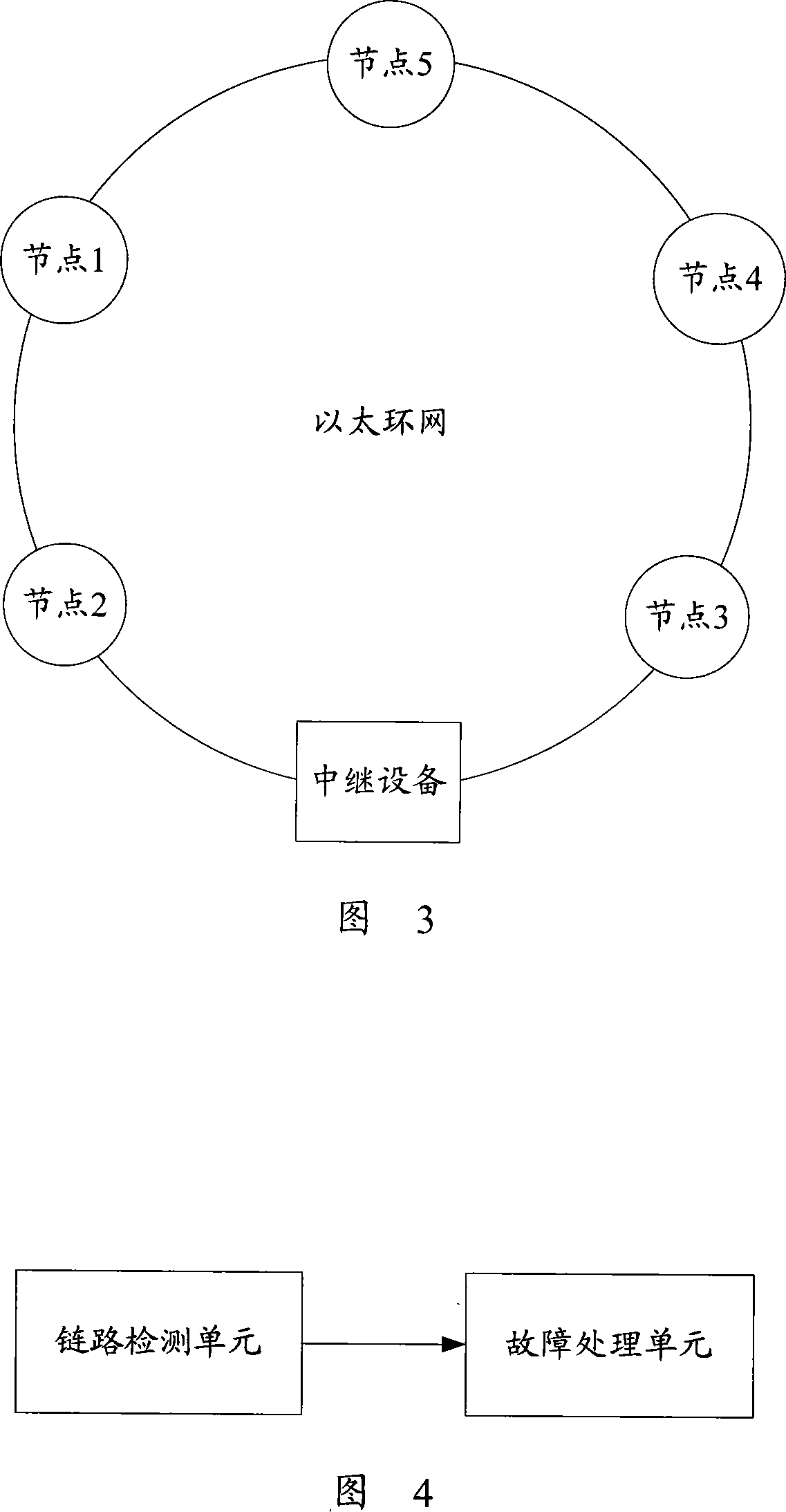
[0029] In order to overcome the defects of the prior art, the present invention proposes an Ethernet ring network protection method for an Ethernet ring network including a relay device, the process of which is shown in Figure 2 and mainly includes the following steps:

[0030] Step 201: Select a node on both sides of the relay device that is closest to the relay device and supports high-speed link detection.

[0031] Wherein, the node supporting high-speed link detection refers to an ordinary node in the Ethernet ring network that supports the Ethernet ring network protocol at the same time, rather than a relay device, they support high-speed link detection, and can actively report when a link fails The LINK_DOWN message notifies the master node.

[0...


PUM


Abstract

The invention provides a method for protecting an Ethernet. The method is used for the Ethernet comprising trunk equipment and comprises the following steps: nodes which are close to the trunk equipment and support the high speed link detection are chosen on two sides of the trunk equipment; the relay transmission link state between the two chosen nodes are detected; when the failure of the relay transmission link is detected, one interface which is positioned on one chosen node and connected with the failure link is blocked and a link failure message is reported to a main node; after the main node receives the link failure message, an auxiliary interface is opened. In addition, the invention also provides an Ethernet protection system and a node. The technical proposal provided by the invention can realize quick protection switching and avoid the generation of a ring circuit in the Ethernet comprising the trunk equipment.

Description

technical field [0001] The invention relates to ring network protection technology, in particular to an Ethernet ring network protection method, system and device including relay equipment. Background technique [0002] In view of many advantages such as fast protection switching and strong fault self-healing capability, the Ethernet ring network technology has been favored by more and more operators in recent years. FIG. 1 shows a schematic diagram of the Ethernet ring network structure, including a master node (Master Node) and multiple transit nodes (Transit Node), which form a ring structure. The master node is connected to the two ports on the ring, one of which is called the primary port (Primary Port), and the other is called the secondary port (Secondary Port). Under normal circumstances, the master node only opens the primary port and blocks the secondary port to avoid a loop and form a broadcast storm; when the loop fails, the primary node opens the secondary port...

Claims


Application Information

Patent Timeline
IPC IPC(8): H04L12/42H04L12/24
Inventor 王明辉赵里遥
Owner NEW H3C TECH CO LTD
Learn More