Supercharge Your Innovation With Domain-Expert AI Agents!

Joint lever for adsorption tower

A technology of connecting rods and adsorption towers, applied in the field of pressure swing adsorption gas devices, to achieve the effect of low wall-attachment effect and high gas purity

Inactive Publication Date: 2008-07-23
无锡市华灵过滤设备有限公司
View PDF1 Cites 0 Cited by
  • Summary
  • Abstract
  • Description
  • Claims
  • Application Information

AI Technical Summary

Problems solved by technology

[0002] With the improvement of people's living standards, people's awareness of the importance of ambient air quality is also increasing. Air separation and adsorption devices are gradually entering the field of people's lives from the production field. Among the devices that separate and adsorb gases, the adsorption tower It is the core device wherein, it is directly related to the purity and the flow rate of the product gas, and the traditional adsorption tower, such as the inventor's previous invention patent authorization announcement number CN1055273C, the announcement date was August 9, 2000, and the invention title is "One A device for preparing nitrogen-enriched gas ", the gas inlet and outlet are directly set on the adsorption tower, after the gas inlet and outlet are set in this way, after the gas enters the adsorption tower, a radial flow is formed in the tower, and the gas flow The sticking effect is more obvious

Method used


Image

  • Joint lever for adsorption tower
  • Joint lever for adsorption tower
  • Joint lever for adsorption tower

Examples


Embodiment Construction

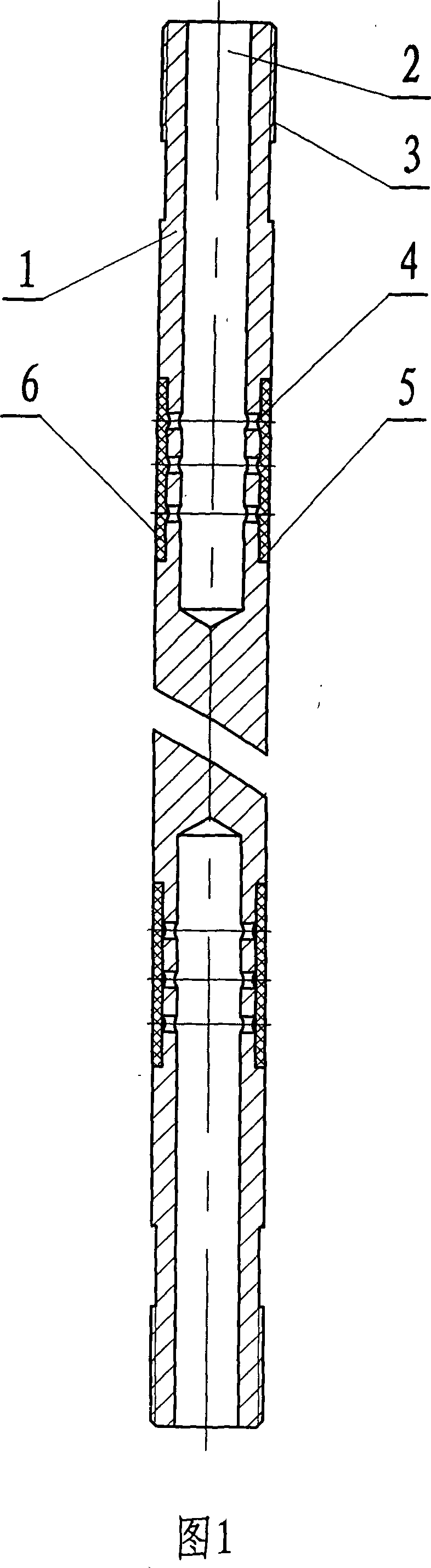
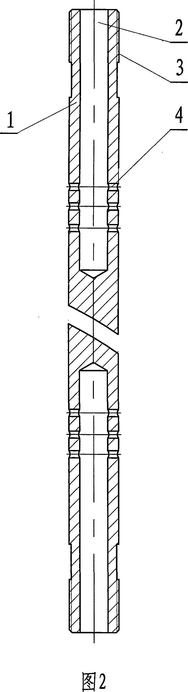
[0012] Below in conjunction with accompanying drawing, the present invention will be further described

[0013] The two ends of a connecting rod 1 for an adsorption tower shown in Fig. 1 are each provided with an axial blind hole 2, and a radial hole 4 is connected between the axial blind hole and the outer circumferential surface of the connecting rod, and the radial hole is opposite to the connecting rod. Axisymmetric distribution, the diameter of the radial hole is greater than or equal to 0.2 mm, the diameter of a section of the outer circle of the connecting rod with the radial hole is 5 less than the diameter of other parts of the connecting rod, and the outer circumferential surface of the radial hole is wrapped with a filter net6.

[0014] Threads 3 are provided at the outer circles of both ends of the connecting rod, the material of the connecting rod is stainless steel, the material of the filter net is also stainless steel, and the number of the radial holes is 3 pa...


PUM

PropertyMeasurementUnit
Apertureaaaaaaaaaa
Apertureaaaaaaaaaa

Abstract

The invention relates to a transformation gas-adsorption device, in particular to a part used for an adsorption tower; the invention aims at solving a technical problem about how to provide an adsorption tower part which can lead the gas in tower to be properly distributed to form an axial flowing with a low wall-sticking effect but high gas purity. An axial blind hole is respectively arranged at two end faces of a connecting rod used for the adsorption tower, and outer circle faces of the axial blind hole and connecting rod are communicated through radial holes which are symmetrically arranged against the axis of the connecting rod. When the aperture of the radial hole is greater than or equal to 0.2mm, a round groove the diameter of which is less than that of other parts of the connecting rod is arranged on the outer circle of the connecting rod where the radial hole is cut, and an outer circle face of the round groove is covered by a strainer. If the aperture of the radial hole is less than 0.2mm, the covering of strainer can be avoided. Outlets and inlets used for air adsorption and desorption of the adsorption tower are all arranged on the connecting rod so as to lead the gas to flow into the adsorption tower through the axial blind hole and the radial hole on the connecting rod, so as to lead the gas to flow axially in the tower with low wall-sticking effect but high purity of separated gas, and the gas purity can be over 96 percent after measurement.

Description

technical field [0001] The invention relates to a pressure swing adsorption gas device, in particular to a component for an adsorption tower. Background technique [0002] With the improvement of people's living standards, people's awareness of the importance of ambient air quality is also increasing. Air separation and adsorption devices are gradually entering the field of people's lives from the production field. Among the devices that separate and adsorb gases, the adsorption tower It is the core device wherein, it is directly related to the purity and the flow rate of the product gas, and the traditional adsorption tower, such as the inventor's previous invention patent authorization announcement number CN1055273C, the announcement date was August 9, 2000, and the invention title is "One A device for preparing nitrogen-enriched gas ", the gas inlet and outlet are directly set on the adsorption tower, after the gas inlet and outlet are set in this way, after the gas enter...

Claims


Application Information

Patent Timeline
IPC IPC(8): B01D53/04
Inventor 黄公连冯华南杨耀峰
Owner 无锡市华灵过滤设备有限公司
Features
  • R&D
  • Intellectual Property
  • Life Sciences
  • Materials
  • Tech Scout
  • Unparalleled Data Quality
  • Higher Quality Content
  • 60% Fewer Hallucinations
Learn More