Wall-attachment fluidic sprinkler

A wall-attached jet and nozzle technology, applied in the direction of spraying devices, spraying devices, spraying devices with movable outlets, etc., can solve the problems of complex reverse mechanism, gas-water separator can not work normally, fan-shaped spraying function can not be completed, etc. Achieve stable and reliable results

Inactive Publication Date: 2008-07-23
JIANGSU UNIV
View PDF2 Cites 43 Cited by
  • Summary
  • Abstract
  • Description
  • Claims
  • Application Information

AI Technical Summary

Problems solved by technology

The "double-click synchronous full-jet nozzle" uses an orifice to control the intermittent interception of signal water in the signal water nozzle, and the reverse mechanism is relatively complicated
In the "full jet nozzle", the air is supplied by the air supply hole of the air-water separator, and the air-water separator will not work properly due to blockage
The "full jet micro-sprinkler" nozzle relies on the taper to drive the nozzle to rotate, and cannot complete the fan-shaped spraying function

Method used


Image

  • Wall-attachment fluidic sprinkler
  • Wall-attachment fluidic sprinkler
  • Wall-attachment fluidic sprinkler

Examples


Embodiment 1

[0018] Example 1: The signal water nozzle is set in the working area of ​​the component cavity. The working process of water intake is as follows:

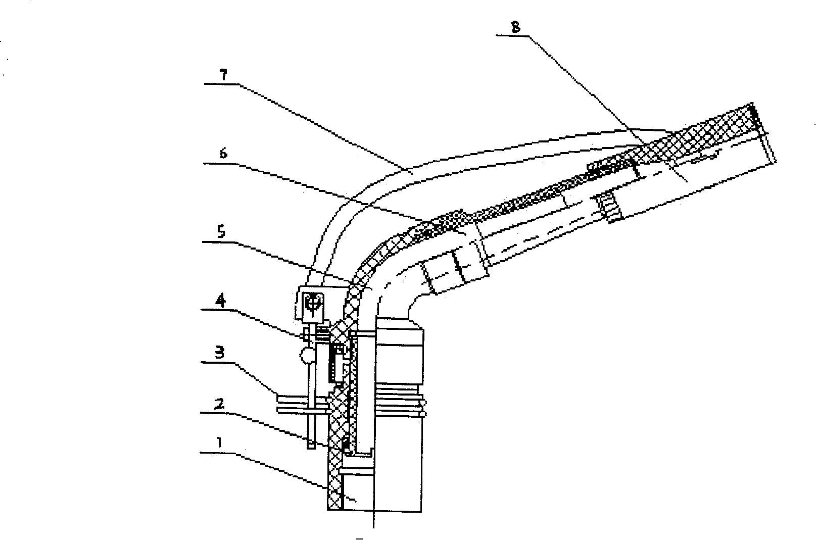
[0019] Direct state: such as Figure 5 As shown, the water flow is sprayed from the hole D into the action area, from Figure 4 It can be seen from the A-direction view that the main jet is ejected from the central hole, and the left and right ends of the main jet are separated from each other, and the air at both ends cannot circulate. The reverse air supply nozzle (9) on the left side of the water jet element body is open, so as to supply air to the left cavity, and the gap C between the outlet on the right side of the element and the water beam is filled with air, so the pressure on the left and right sides is basically equal , the main jet is in a direct state, and the nozzle is stationary. At the same time, the signal water nozzle (10) has obtained signal water on the left edge of the water beam, and the signal water obtain...

Embodiment 2

[0022] Example 2: The signal water nozzle is set outside the cover plate, and the water intake process is as follows:

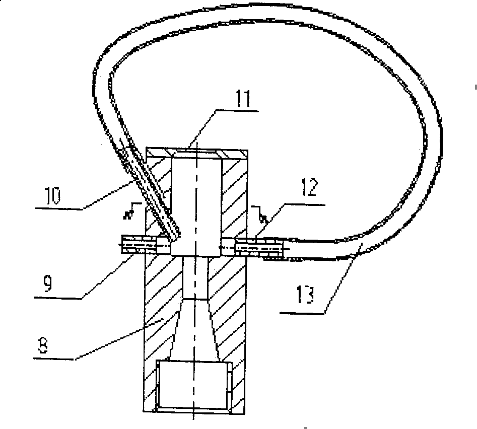
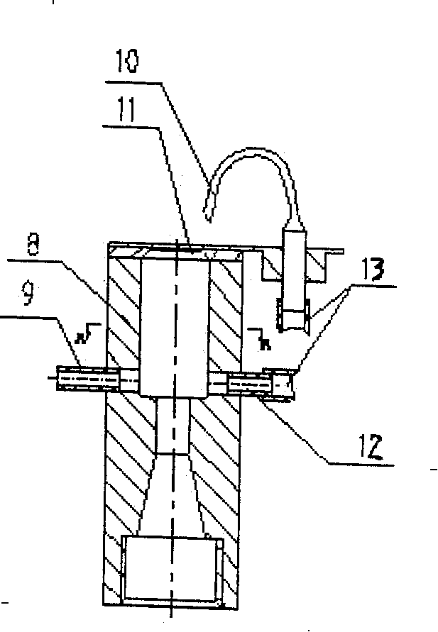
[0023] The water flow is injected into the action area from the hole D, and the left and right ends of the action area form a low-pressure vortex area. The left side of the nozzle is supplied with air by the reverse air nozzle (9) through the reverse plastic pipe (7), and the right side is supplied with air by the signal water connector (10). The pressure on both sides is equal, the water flow is direct, and the nozzle is still. The signal water is taken out from the signal water connector (10) and flows into the signal water inlet nozzle (12), so that no air is added to the right side, and a low-pressure vortex area is formed on the right side, and the pressure on the left side is higher than that on the right side. The chamfering of the outlet cover plate (11) produces a driving force on the shower head to make the shower head rotate step by step. At this ...


PUM


Abstract

The invention pertains to a key equipment for water-saving irrigation, which is a wall-attached fluidic sprinkler, comprising a sprinkler body, a thrust jet, a rotary sealing mechanism, a spacing ring, a reversing mechanism and a fluidic element body. The sprinkler is characterized in that the fluidic element consists of a reverse gulp nozzle, a signal water joint nozzle, an outlet cover, a signal water entry nozzle and a draft tube; on the outer wall of the fluidic element body, the signal water joint nozzle and the reverse gulp nozzle positioned below signal water joint nozzle are arranged at one side; the signal water entry nozzle is arranged at the other side. The signal water joint nozzle and signal water entry nozzle are connected by the draft tube; the outlet cover is arranged at the upper end of the fluidic element body. The signal water inside the signal water joint nozzle causes one side of the main fluid to form a low pressure vortex region discontinuously. The opening and closing of the gulp nozzle causes another side of the main fluid to switch between high pressure and low pressure, thus forming pressure difference between two ends of the main fluid to realize water attaching and complete direct jetting of the nozzle, stepping and reverse running of the sprinkler.

Description

technical field [0001] The invention belongs to key equipment in a water-saving irrigation sprinkler irrigation system, in particular to a wall-attached jet-flow sprinkler head. Background technique [0002] At present, the shortage of fresh water resources is a major problem in the world, and sprinkler irrigation has become an important means of sustainable agricultural development. The sprinkler head is the key equipment of the sprinkler irrigation system, and its performance directly affects the sprinkler irrigation effect. The most widely used rotary nozzle is the rocker nozzle, which has a complicated structure and low energy conversion rate. Now, the jet has established a new position in the control technology, and foreign scholars have not used jet technology to develop nozzles. [0003] After retrieval, the relevant mid-term patents currently include Han Xiaoyang et al. utility model patent "double-click synchronous full jet nozzle" 90200784.X, Xie Fuqi et al. util...

Claims


Application Information

Patent Timeline
Patent Type & Authority Applications(China)
IPC IPC(8): B05B3/02B05B1/34B05B15/04
CPCB05B3/06B05B3/16
Inventor 袁寿其李红朱兴业向清江张杰刘俊萍谢福祺
Owner JIANGSU UNIV
Why Eureka
Try Eureka