Electric spanner for vehicle

A technology for electric wrenches and vehicles, applied in power tools, manufacturing tools, etc., can solve the problems of breakage and damage of impact blocks and bumps, accelerated impact of impact blocks, and mismatched motion trends, so as to reduce breakage damage and speed up meshing. speed, and the effect of improving the service life

Inactive Publication Date: 2008-07-23
ZHEJIANG SHENGUANG ELECTRICAL
View PDF0 Cites 3 Cited by
  • Summary
  • Abstract
  • Description
  • Claims
  • Application Information

AI Technical Summary

Problems solved by technology

Due to the unreasonable setting position of the steel ball 200a which acts as a limiter, the movement trajectory of the steel ball does not match the movement trend of the impact block 40a, not only the impact block cannot achieve the purpose of accelerated impact, but also the engagement surface of the impact block will appear 701a and the protrusion shoulder 103a are not in place, that is, the innermost end of the engagement surface 701a of the impact block cannot reach the shoulder root 104a of the protrusion, causing only a local force on the outer layer of the protrusion 103a, which is easy to cause The impact block and the bump are broken and damaged, which shortens the service life of the electric wrench

Method used


Image

  • Electric spanner for vehicle
  • Electric spanner for vehicle
  • Electric spanner for vehicle

Examples


Embodiment Construction

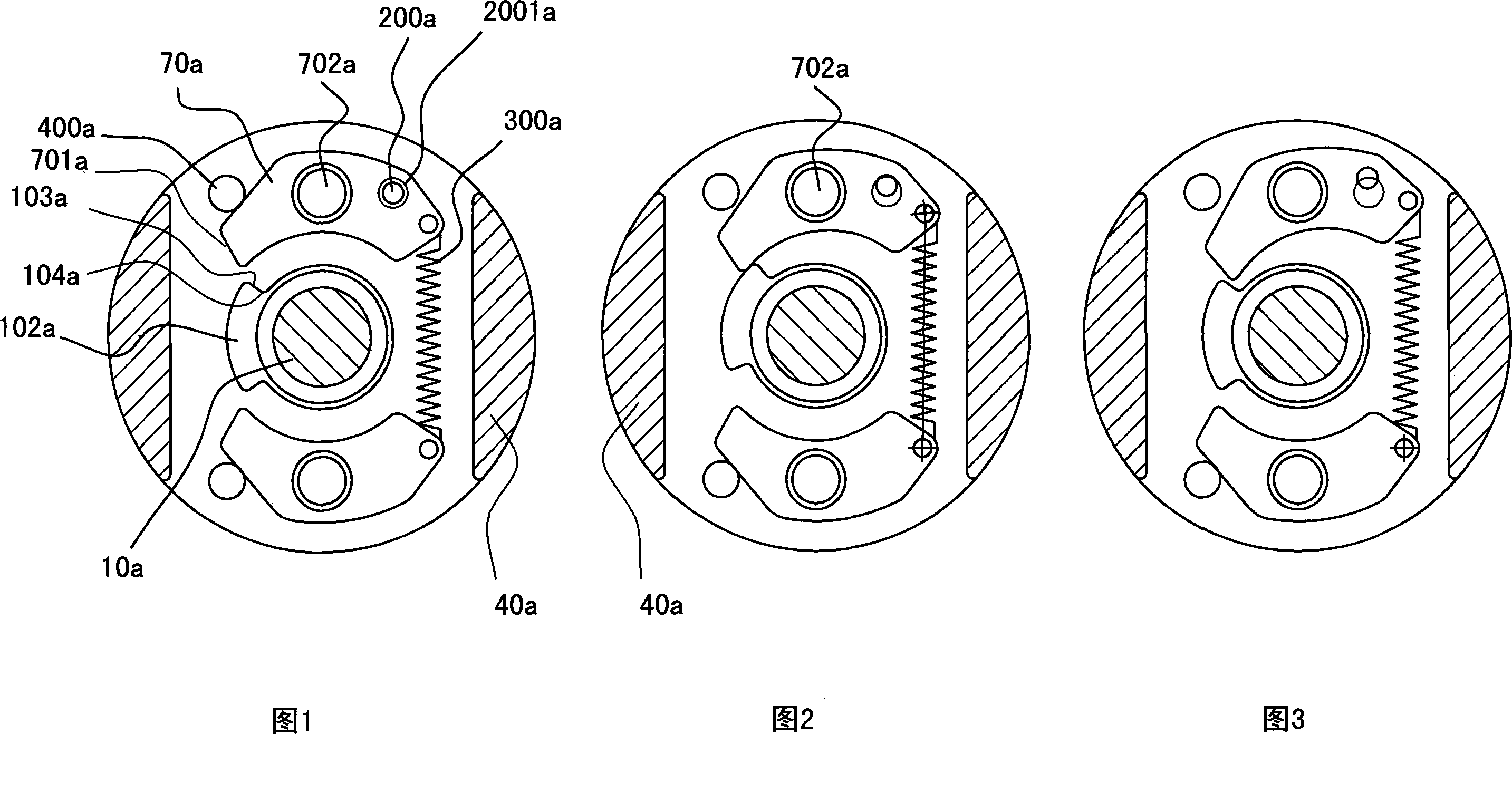
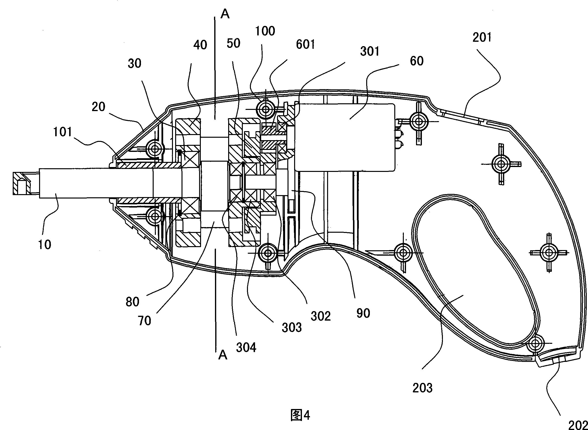
[0030] See Figure 4. The wrench of the present invention includes a casing 20, a bushing 101, a motor 60, a clutch 50, a flywheel 40, an output shaft 10 and the like. All parts are placed in the casing 20, and the casing is composed of upper and lower parts, which are fixed together by fixing bolts through a plurality of fixing seats 100. The output shaft 10 protrudes out of the casing 20, and the front of the outer end of the output shaft 10 forms a shape consistent with the work object, such as a sleeve shape, which is convenient to be connected with a fastener. All other parts are all fixedly positioned on the bracket 90 of the casing inner wall, and the DC12 DC motor 60 is connected with the inner kinematic pair including the pinion 601 through the motor shaft, and drives the flywheel 40 after the speed change. The flywheel is installed on the inner wall of the casing through a bearing at one end and a support sleeve at one end.

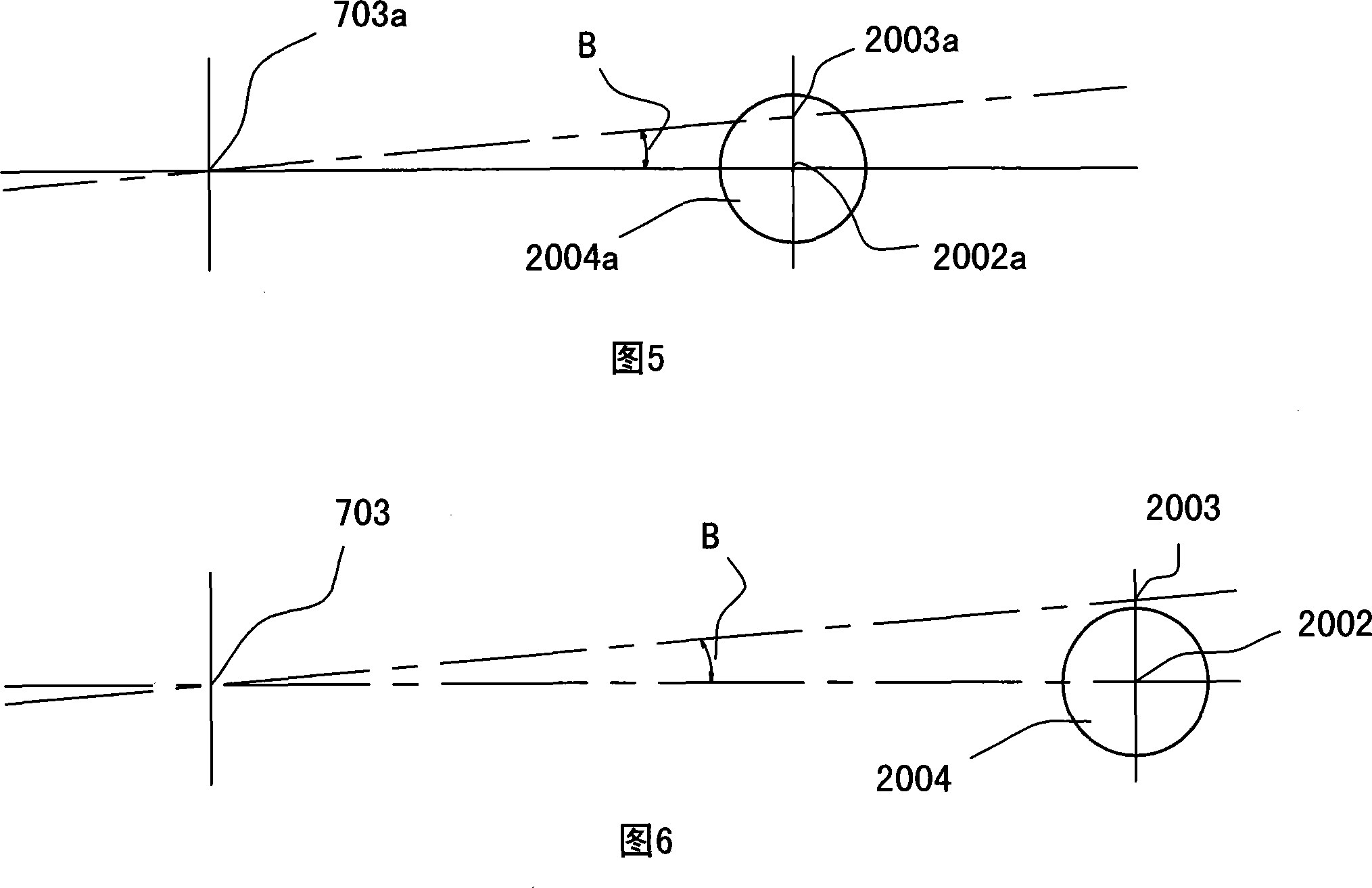
[0031] Referring to FIG. 7 , the flywhee...


PUM


Abstract

The invention provides an on-board electric wrench, comprising a flywheel, an output shaft, a lug boss and an impact block. A pin shaft which is used for positioning the impact block is sheathed with a torsion spring; two forcing ends of the torsion spring are respectively positioned on a position limit retaining pin and the impact block; the distance between the center of the positioning hole of a steel ball and the center of the pin shaft complies with the requirement that the chord length corresponding to the motion track of the steel ball is more than the radius of the positioning hole of the steel ball. The invention replaces a pulling spring with the torsion spring, changes the adjusting position, leads the adjustment of the impact force and the recovery force of the impact block to be realized by the rigidity of the torsion spring and the steel ball supporting spring respectively, solves the contradiction that adjustment of the impact force and the recovery force of the impact block is integrated into a whole on the pulling spring, meets the impact force of the wrench design, leads the recovery of the impact block to be slow, leads the engagement surface of the impact block can always push through the forcing surface of the convex block and convex shoulder before the screw is screwed or after the screw is loosened so as to achieve the continuous operation, and has the advantages of fully automation of loosening and tightening the screw, complete engagement of the impact block and the root of the convex block, and long service life.

Description

【Technical field】 [0001] The invention belongs to an electric wrench for a vehicle, in particular to an electric wrench for a vehicle using a vehicle storage battery as a power source. 【Background technique】 [0002] The electric wrench, which uses the car battery as the power source, is a car-carrying tool, which is favored by consumers for turning manual elastic and firm parts into electric operations. The application area is also becoming more and more extensive with the development and popularization of the automobile industry. [0003] Chinese Patent No. 032291744 "a two-way impact electric and pneumatic wrench" is a typical electric wrench at present. Referring to Fig. 1 (this figure is a cross-sectional schematic diagram of flywheel 40a), when working, it uses a DC12V DC motor to use a car battery (cigarette lighter seat) as a working power supply, and drives the flywheel to rotate through the motor shaft and its gear pair engaging the clutch The flywheel is embedded...

Claims


Application Information

Patent Timeline
Patent Type & Authority Applications(China)
IPC IPC(8): B25B21/02
Inventor 王骏魏巍
Owner ZHEJIANG SHENGUANG ELECTRICAL
Why Eureka
Try Eureka