Gathering type solid-liquid separation machine
A technology of solid-liquid separator and rack, which is applied in filtration separation, separation method, fixed filter element filter, etc. Equipment cost and operating energy consumption, good rigidity, and the effect of increasing water flow
- Summary
- Abstract
- Description
- Claims
- Application Information
AI Technical Summary
Problems solved by technology
Method used
Image
Examples
Embodiment 1
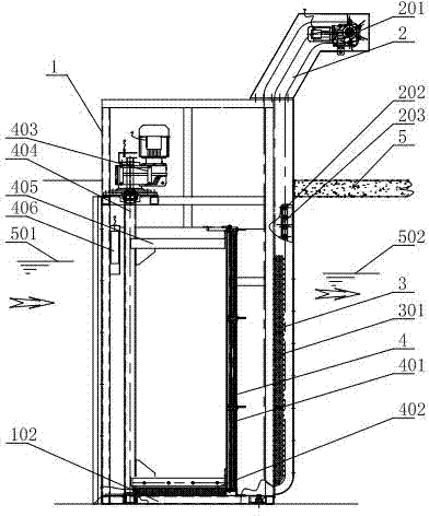
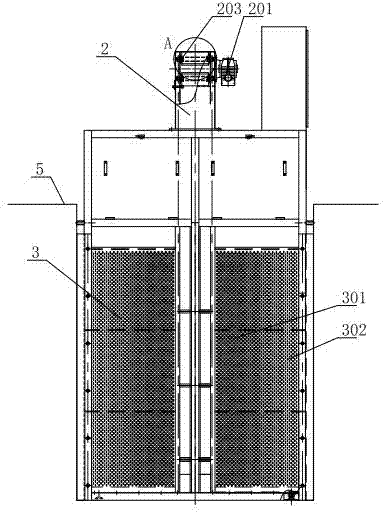
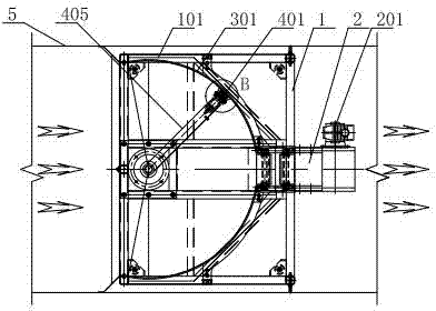
[0034] Such as Figure 1 to Figure 3 As shown, the filter device 3 is composed of two arc filter plates 301 of nearly 1 / 4 circular arc surface, and the filter plate fixing side frame 101 of the frame 1 is vertically fixed on the cross section of the water channel 5, and its concave The inlet face faces the water inlet side; the surface of the curved filter plate 301 is densely covered with filter holes 302, and the diameter of the filter holes 302 is determined according to the water flow and impurities. In this embodiment, the diameter of the filter holes is 2mm. The slag extracting device 2 is arranged between the two arc-shaped filter plates 301, located in the center of the cross-section of the water channel 5, and the width accounts for about 20% to 30% of the cross-section of the water; the structure of the slag extracting device 2 in this embodiment is similar to Existing rotary grid cleaning machines, such as Figure 4 The slag extraction and dehydration grid assembly...
Embodiment 2
[0041] Such as Image 6 , Figure 7 As shown, the filter hole slag cleaning device 4 of the present embodiment is a vacuum suction structure, and other components are the same as those of the first embodiment. The vacuum pump 411 and the vacuum storage tank 412 are arranged on the top of the frame 1, and the position of the roller brush hole cleaner 401 is set in the first embodiment. The slag rotating main shaft 404 and the pipeline inside the slag cleaning rotating arm 405 are connected with the vacuum pump 411 and the vacuum storage tank 412, and an electric ball valve 413 is provided to realize the opening and closing of the pipeline, and the slag cleaning rotating main shaft 404 is realized through the rotating seal 414 when it rotates connected to the vacuum system. Such as Figure 7 As shown, the opening of the vacuum suction nozzle 415 faces the curved filter plate 301 , and forms a relatively airtight space under the closure of the plastic scraping strips 408 on bo...
Embodiment 3
[0043] Such as Figure 8 As shown, the slag extraction device 2 of this embodiment is a screw slag extraction structure, and other components are the same as those of the first embodiment. The slag extraction motor 201 drives the rotation of the bidirectional or unidirectional screw screw 206, and the slag extraction scraper 205 fitted on the screw screw 206 by the screw nut moves up and down to filter the lower part of the water body filter device 3 and collect the grid slag at the end Elevate to the upper part, and scrape and remove it into the slag hopper on the upper part of the water channel 5 by the slag unloading scraper 204 swinging on the top for processing.
PUM
 Abstract
Description
Claims
Application Information
 - R&D
- Intellectual Property
- Life Sciences
- Materials
- Tech Scout
- Unparalleled Data Quality
- Higher Quality Content
- 60% Fewer Hallucinations
Browse by: Latest US Patents, China's latest patents, Technical Efficacy Thesaurus, Application Domain, Technology Topic, Popular Technical Reports.
© 2025 PatSnap. All rights reserved.Legal|Privacy policy|Modern Slavery Act Transparency Statement|Sitemap|About US| Contact US: help@patsnap.com


