Supercharge Your Innovation With Domain-Expert AI Agents!

Shuttle type difference decompression valve

A pressure relief valve and shuttle technology, applied in the field of pressure relief valves, can solve the problems of ineffective take-off, large volume, ineffective return seat, etc., and achieve the effects of good symmetry and coaxiality, small overall volume and reliable operation.

Inactive Publication Date: 2008-07-23
WINJET HIGH TECH INVESTMENT BEIJING
View PDF0 Cites 2 Cited by
  • Summary
  • Abstract
  • Description
  • Claims
  • Application Information

AI Technical Summary

Problems solved by technology

[0002] Due to the unreasonable structure and large size of the existing pressure relief valve, it is prone to failure to take off and return to the seat. It is unsafe to use, and accidents will damage the environment and affect life safety.

Method used


Image

  • Shuttle type difference decompression valve

Examples


Embodiment Construction

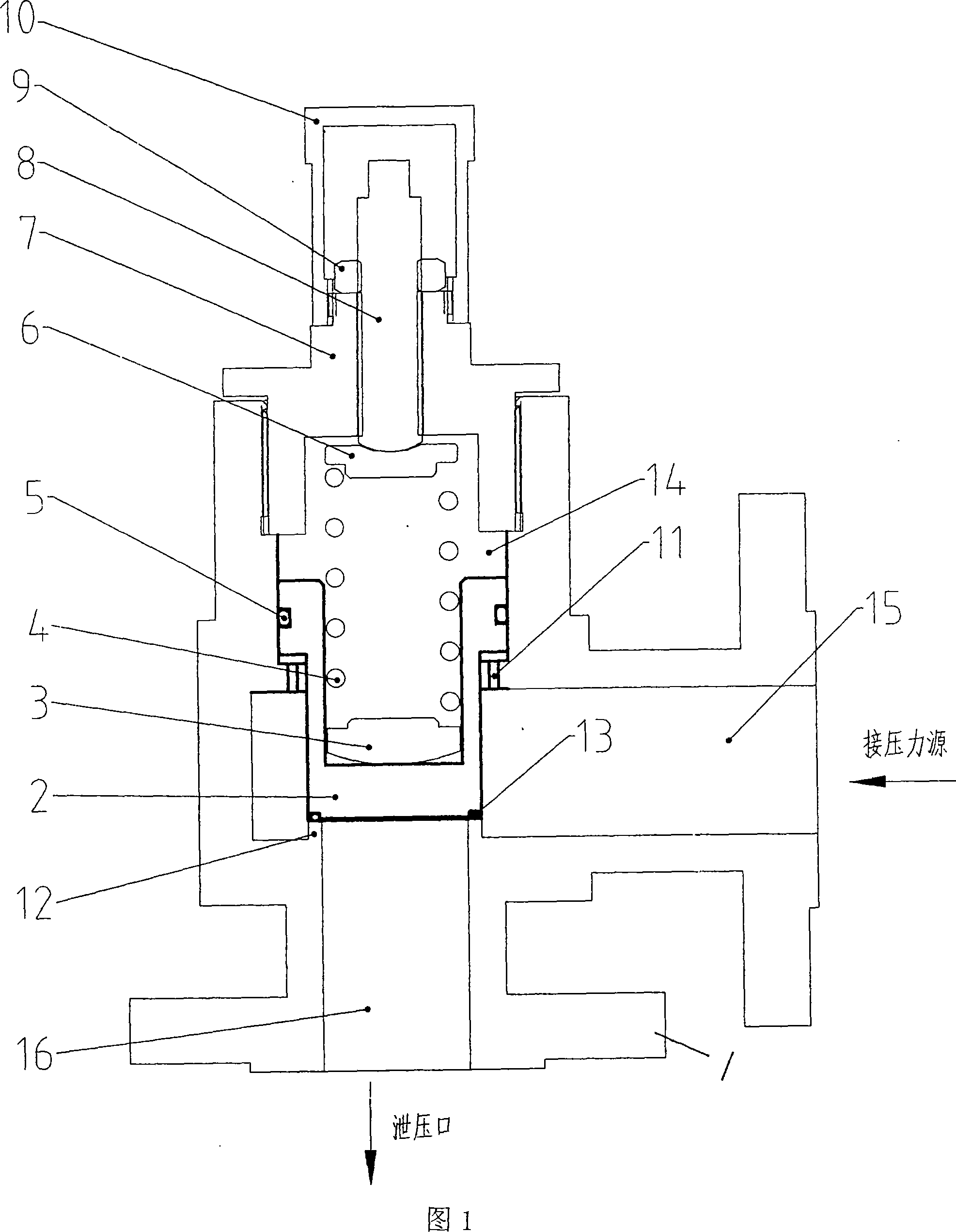
[0019] The valve body 1 is threadedly connected with the valve cover 7 . The spring adjusting rod 8 is threadedly connected with the inner hole of the valve cover 7 and has a locking nut 9 . The outer cover 10 is connected with the valve cover 7 and closes the upper end of the spring adjusting rod. The valve disc 2 is shuttle-shaped, and an arc-shaped spring seat 3 is connected with the lower end of the spring 4 on the inner cavity bottom plate, and the upper end of the spring 4 is connected with the lower end of the spring adjusting rod through the spring seat 6 . An annular space is formed between the step of the valve flap 2 and the stepped surface of the inner flange of the shuttle chamber 14 , and the space communicates with the pressure channel 15 of the valve body through the evenly distributed communication holes 11 on the inner flange of the shuttle chamber 14 . There is a valve seat 12 at the inner end of the discharge channel 16 of the valve body, and a sealing rin...


PUM


Abstract

The invention relates to a shuttle differential relief valve to solve the problems of large bulk and ineffective take-off and return in prior relief valve body. a valve base (12) and a valve clack (2) sealing fitted with each other are arranged on the internal end surface of a discharging channel (16)of a valve body (1) ; the large diameter segment of the upper end of the valve clack (2) is sliding fitted with a shuttle cavity (14); a sealing ring (5) is arranged in a rabbet on outer wall of the valve clack big end; the small diameter segment of the valve clack (2) is sliding fitted with an inner flange at lower end of the shuttle cavity (14); a through hole (11) in the inner flange is communicated with the shuttle cavity (14) and a pressure channel (15); a spring (4) in an intracavity at big end of the valve clack (2) is connected with a spring regulating rod (8) thread-fitted with a valve cap (7) and the valve cap (7) is connected with the valve body (1).

Description

Technical field: [0001] The present invention relates to a pressure relief valve on a pressure line of a pressure vessel. Background technique: [0002] Due to the unreasonable structure and large volume of the existing pressure relief valve, it is easy to fail to take off and return to the seat. It is not safe to use, and accidents will damage the environment and affect life safety. Invention content: [0003] The purpose of the present invention is to provide a shuttle type differential pressure relief valve with simple and reasonable structure, small volume, sensitive take-off and reseat, and good sealing performance. [0004] The present invention is achieved like this: [0005] In the shuttle type differential pressure relief valve of the present invention, the inner end surface of the discharge channel 16 of the valve body 1 has a valve seat 12 that is in sealing fit with the valve disc 2, the large diameter section at the upper end of the valve disc 2 is slidingly ...

Claims


Application Information

Patent Timeline
Patent Type & Authority Applications(China)
IPC IPC(8): F16K17/04
Inventor 曾祥炜
Owner WINJET HIGH TECH INVESTMENT BEIJING
Features
  • R&D
  • Intellectual Property
  • Life Sciences
  • Materials
  • Tech Scout
  • Unparalleled Data Quality
  • Higher Quality Content
  • 60% Fewer Hallucinations
Learn More