Wheel bearing arrangement having spur toothing

A technology of wheel bearings and end teeth, which is applied in the direction of rotating bearings, bearings, wheels, etc., can solve the problem of wheel train tipping and other problems, and achieve the effect of large diameter and high driving torque

Active Publication Date: 2008-07-23
SCHAEFFLER TECH AG & CO KG
View PDF1 Cites 4 Cited by
  • Summary
  • Abstract
  • Description
  • Claims
  • Application Information

AI Technical Summary

Problems solved by technology

The lower the rigidity of the bearings, the more easily the loads can lead to tipping of the wheel train, which have a negative e

Method used


Image

  • Wheel bearing arrangement having spur toothing

Examples


Embodiment Construction

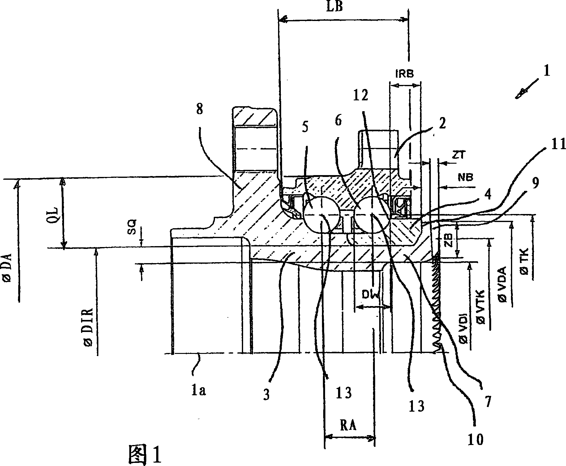
[0055] Figure 1 shows an embodiment of the invention.

[0056] The wheel bearing arrangement 1 is formed from a vehicle-side flange 2 , a hub 3 with a wheel flange 8 , an inner ring 4 and two rows 5 , 6 of rolling bodies. In this case the balls 12 of the two rows 5 and 6 are arranged around the axis of rotation of the wheel bearing unit 1 with a pitch circle of diameter TK. The pitch circle extends through the ball center 13 .

[0057] The inner ring 4 rests on a hollow section 7 with a wall thickness SQ. This section 7 has an inner diameter VDI. A collar 9 is formed integrally with section 7 of hub 3 . The collar 9 is located radially away from the segment 7 and has an outer diameter VDA on the outside.

[0058] The wheel bearing arrangement 1 , here the inclined ball bearing arrangement, is clamped via the collar 9 . To this end, the collar 9 bears axially against the end face 11 of the inner ring 4 in the direction of the end toothing 10 . The width IRB of the shoulde...


PUM


Abstract

The invention relates to a wheel bearing arrangement having at least two rows of rolling bodies for supporting a wheel hub drivable by the wheel bearing arrangement via a drive element. The wheel hub is connected to the drive part; the wheel hub and the drive part mesh with each other in a form-locking manner via a pair of mutually corresponding end face gears. On the wheel bearing arrangement, in particular, the ratio of the pitch circle diameter (VTK) of the wheel bearing arrangement-side toothing to the rolling element row distance (RA) of the at least two rows of rolling elements is greater than a value of three.

Description

technical field [0001] The invention relates to a wheel bearing arrangement having at least two rows of rolling bodies for supporting a wheel hub drivable by the wheel bearing arrangement via a drive element, wherein the wheel hub is connected to the drive element and the wheel hub and the drive element are connected by means of a pair of mutually corresponding end faces The teeth intermesh in a form-locking manner. Background technique [0002] Such a wheel bearing arrangement with face toothing and the function of the face toothing are described in detail in DE 3116720 C1. As is also known from DE 3116720 C1, the face toothing can be applied to the hub, for example, by chip-free machining. [0003] The connection between the wheel hub and the drive element via the front toothing saves construction space and can transmit relatively high torques, but its application is limited due to the size of the wheel bearing arrangement. [0004] Furthermore, known wheel bearing arran...

Claims


Application Information

Patent Timeline
IPC IPC(8): B60B27/00F16C43/04F16D1/076
CPCB60B27/0005F16D1/076F16C43/04B60B27/0084B60B27/0094F16D1/033F16C19/186F16C2326/02F16C2240/40B60B27/00
Inventor P·尼布林E·马苏尔R·朗格尔
Owner SCHAEFFLER TECH AG & CO KG
Why Eureka
Try Eureka