Sensor for monitoring and controlling termite system

A monitoring control and sensor technology, which is applied in the field of termite control devices, can solve the problems of corrosion and fracture of electrical conduction lines, termite erosion, installation difficulties, etc., and achieves the effects of low cost, good stability, and convenient production and use.

Inactive Publication Date: 2008-07-30
刘文军
View PDF1 Cites 9 Cited by
  • Summary
  • Abstract
  • Description
  • Claims
  • Application Information

AI Technical Summary

Problems solved by technology

Although the system announced by this invention can effectively monitor the appearance of termites, its sensor is a monitoring block covered by plastics, and on the surface of the monitoring block, there are silver particles less than 10 microns of electrical conduction lines to form electrical conductors, such The sensor is extremely fragile in the whole monitoring system. First of all, termite sensors generally need to be buried underground. These electric conductors attached to the surface of the monitoring block are made of electrical conductors with silver particles smaller than 10 microns, making installation very difficult. Moreover, long-term buried The underground termite sensor has a plastic cover to protect the monitoring block, but the long-term damp environment makes these extremely thin electrical conduction lines corroded and broken, or broken by vibration, resulting in the false impression of termite erosion

Method used


Image

  • Sensor for monitoring and controlling termite system
  • Sensor for monitoring and controlling termite system
  • Sensor for monitoring and controlling termite system

Examples


Embodiment Construction

[0017] The present invention will be further described in detail below in conjunction with the accompanying drawings and embodiments.

[0018] Implementation example 1

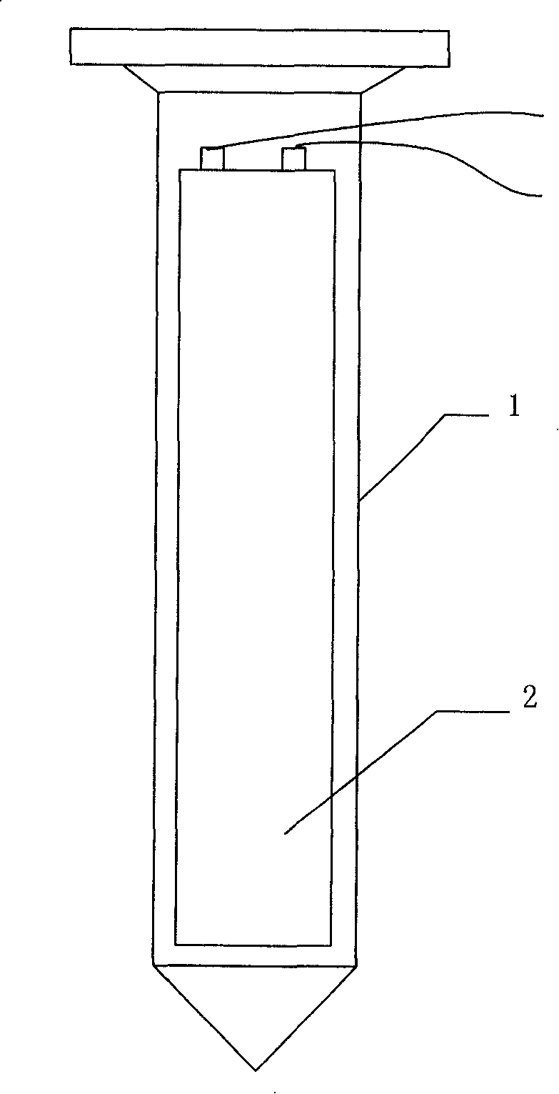
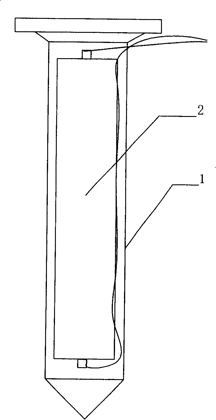
[0019] like Figure 1-2 Shown is a sensor for termite monitoring and control system, the sensor includes a housing body 1, the upper part of which is cylindrical and hollow for accommodating a conductive detection element 2, and the lower part is a solid conical shape, which is convenient for people to bury the sensor in the ground, etc. ;like figure 1 shown.

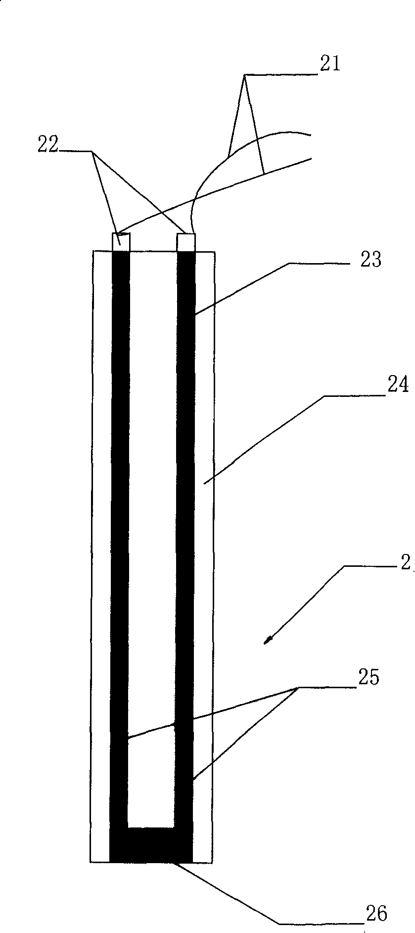
[0020] like figure 2 It is a longitudinal sectional view of the conductive detection element 2, which is columnar and made of termite-loving material 24. There are two through holes 25 in the middle, and the end of the first hole and the head end of the second hole pass through a metal The sheet is connected as an insert, and at the same time, a conductive powder material 23 is pressed into each channel 25, and the terminal end of the first channel...


PUM


Abstract

A sensor used for a termite monitor control system comprises a shell body. At least a conductive detection element is arranged in the shell body. The sensor is characterized in that: the conduction detecting element is made from materials that termites are fond of eating and the middle of the conducting detecting element is provided with at least one perforative channel; a conductive powder material is pressed in the channel; a terminal is arranged on each end of the channel and is connected with a monitoring circuit via a lead to form a conductive loop. Compared with the prior art, the invention has the advantages that: the conductive powder material pressed in the channel of the conductive detection element is used as a conducting medium, which can not affect the conductive property of the conductive powder material owing to the retractility, etc., of materials that the termites are fond of, consequently the sensor is of good stability; in addition, the conductive powder material is tightly wrapped in the materials that the termites are fond of, has a strong adaptation ability to the ambience, and a single detection ability to the termites, thus having a higher inspection accuracy.

Description

technical field [0001] The invention relates to the technical field of termite control devices, in particular to a sensor for a termite monitoring and control system. Background technique [0002] As we all know, although termites are small, they are very harmful, especially to house construction and reservoir dams, etc. The damage is very obvious and the consequences are serious. Some communication facilities in the way of communication have caused great harm. For this reason, people have adopted many methods to eliminate termites, but they often take measures to eliminate them after serious consequences. It can be found and eliminated before it comes to harm. For this reason, the Chinese invention patent "Remote Monitoring System for Detecting Termites" with application number CN97199727.6 discloses a system that can effectively monitor termites in multiple areas. comprising: at least one termite sensor adapted to be placed in each of said zones, each said termite sensor ...

Claims


Application Information

Patent Timeline
Patent Type & Authority Applications(China)
IPC IPC(8): A01M1/00A01M1/20A01M1/02G01R19/00
Inventor 刘文军
Owner 刘文军
Why Eureka
Try Eureka