
Construction for fixing outgoing line of radiating fan

A cooling fan and structure technology, which is applied to components of pumping devices for elastic fluids, non-variable-capacity pumps, machines/engines, etc., can solve the problems of wire 851 coming off, inconvenient assembly, and increased cost of cooling fans, etc. , to achieve the effect of reducing manufacturing costs

Inactive Publication Date: 2008-07-30
SUNONWEALTH ELECTRIC MACHINE IND
View PDF1 Cites 1 Cited by
  • Summary
  • Abstract
  • Description
  • Claims
  • Application Information

AI Technical Summary

Problems solved by technology

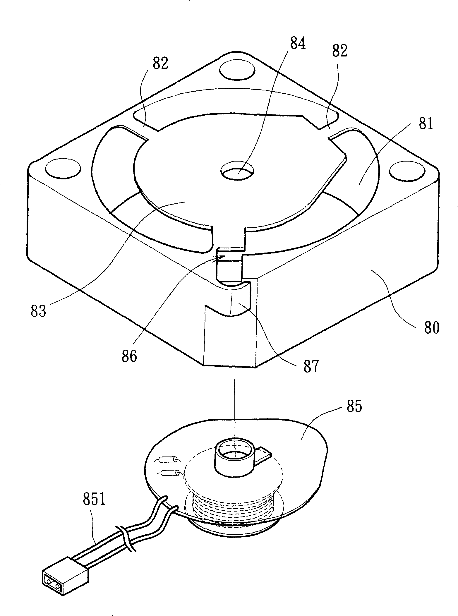
[0004] like figure 1 In the existing wire fixing structure shown, the wire 851 is only fixed by the limiting component 87 at the end of the notch 86. Therefore, when the wire is pulled by an external force, when the wire is directly pulled by an external force, The wire 851 is easy to come out of the opening of the limiting assembly 87, and the fixing effect is not good, so the wire 851 often falls off from the contact position due to pulling
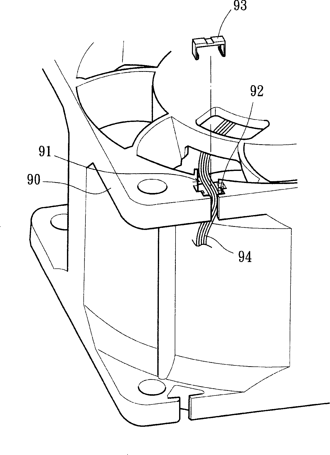
[0005] like figure 2 In the existing wire fixing structure shown, although it utilizes the locking member 93 as a press to fix the wire 94, and it is connected with figure 1 Compared with the wire fixing structure shown, it has a better fixing effect on the wire 94, but because this structure still uses a locking member 93 to press the wire 94 to withstand the pull from the external force, so it is necessary to additionally manufacture the locking member 93, and the locking member 93 needs to be pressed into a transverse guide groove 91 to fix the wire 94, which is inconvenient in assembly and relatively increases the cost of the cooling fan

Method used


Image

  • Construction for fixing outgoing line of radiating fan
  • Construction for fixing outgoing line of radiating fan
  • Construction for fixing outgoing line of radiating fan

Examples


Embodiment Construction

[0028] In order to make the above and other objects, features and advantages of the present invention more comprehensible, preferred embodiments of the present invention will be exemplified below in detail with reference to the accompanying drawings.

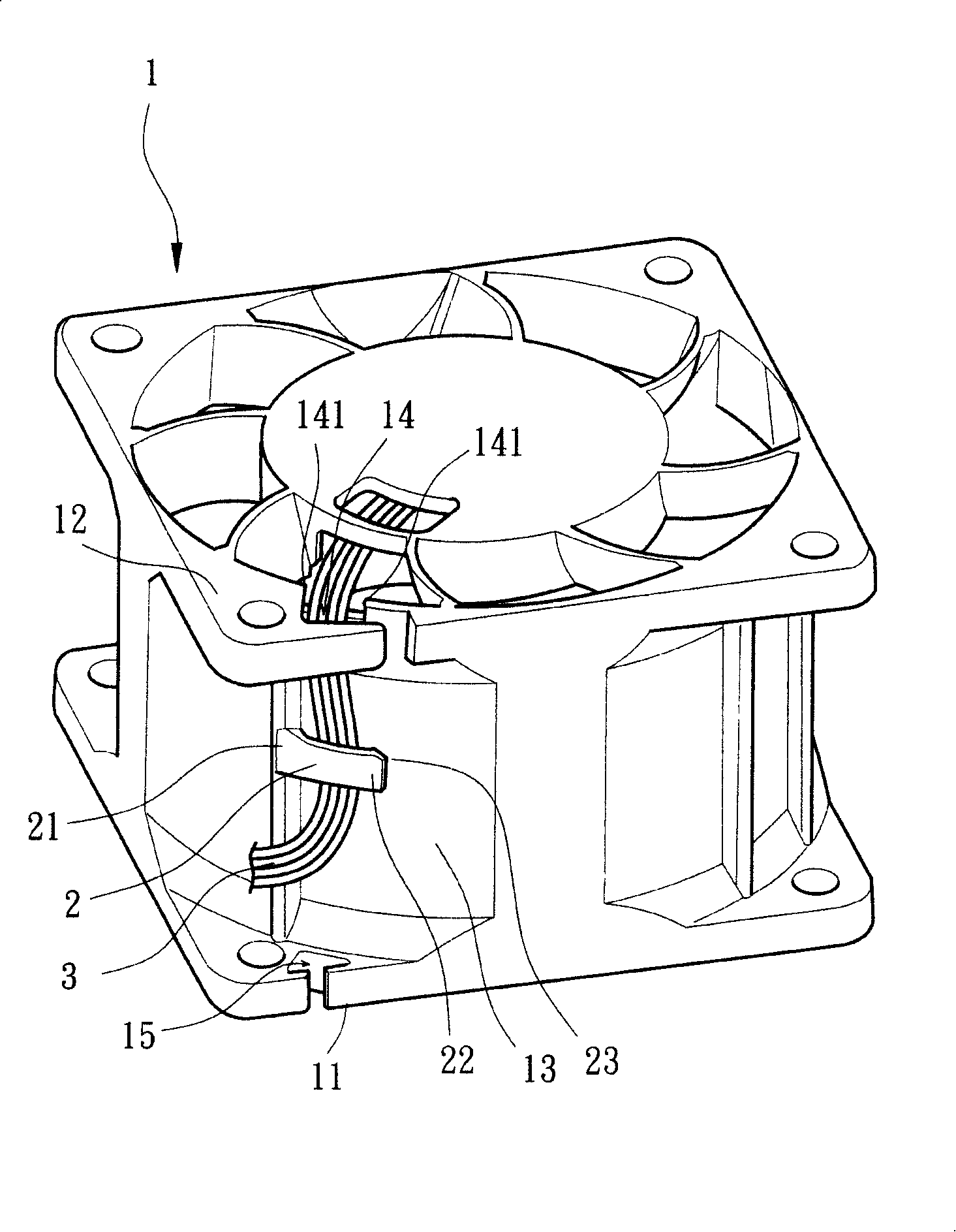
[0029] Please refer to image 3 As shown, it is the outlet fixing structure of a preferred embodiment of the present invention. The cooling fan housing 1 of this embodiment has a first end face 11 and a second end face 12, and between the first end face 11 and the second end face 12 A surrounding side wall 13 is provided, and a through groove 14 is provided on the second end face 12 itself, and the through groove 14 can pass through the second end face 12 for a wire 3 to pass through the second end face 12 and extend toward the side wall 13 . In addition, the through groove 14 is provided with two sides 141 , and the two sides 141 can limit the arbitrary displacement of the wire 3 .

[0030] please refer again image 3 , 4 a...


PUM


Abstract

The invention relates to a line-out fixed structure of a heat dissipation fan. Each of both sides of a casing body forms a first end surface and a second end surface. The casing body between the first end surface and the second end surface is formed from the circumambience of the side wall, and at least one end surface of the casing body is provided with a penetrating wave. The side wall of the casing body is provided with at least a limited component; one end of the limited component is fixed to the side wall, and the other end forms a free end which is not connected with the side wall. A lead-in mouth is formed between the terminal of the free end and the side wall. The casing body of the heat dissipation fan can effectively endure the outside force of dragging a lead to prevent the lead from falling off from a connecting point position because of the drag of the outside force, and can reduce the manufacturing cost of the heat dissipation fan.

Description

technical field [0001] The present invention relates to a wire outlet fixing structure of a heat dissipation fan, in particular to a heat dissipation fan casing, where the lead wire drawn out from the heat dissipation fan casing can be limited and fixed to prevent the wire from being pulled out of its contact. fall off. Background technique [0002] Such as figure 1 As shown, it is the patent application No. 87216621 "Improved Structure of Radiating Fan Shell Seat" in Taiwan, China. The patent is mainly provided with a ventilation hole 81 in the housing 80, and a number of connecting rods 82 are connected to a bottom plate 83 at the position of the ventilation hole 81. A shaft hole 84 is provided in the center of the bottom plate 83 for the combination of the stator base 85. The housing 80 is provided with a notch 86 communicating with the ventilation hole. 83 shaft hole 84, the lead wire 851 of the stator base 85 is drawn out from the notch 86 of the housing 80, and is li...

Claims


Application Information

Patent Timeline
IPC IPC(8): F04D29/52F04D29/64
Inventor 洪银树方美智
Owner SUNONWEALTH ELECTRIC MACHINE IND
Learn More