Method for determining microscopic mechanics performance of each consist composing phase in polyphase material
A multiphase material, micromechanics technology, applied in the direction of analyzing materials, measuring devices, strength properties, etc., can solve problems such as no data point grouping
- Summary
- Abstract
- Description
- Claims
- Application Information
AI Technical Summary
Problems solved by technology
Method used
Image
Examples
Embodiment 1
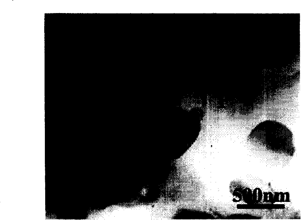
[0060] The multiphase material to be tested is spheroidized annealed GCr15 bearing steel, and its microstructure is as follows: figure 2As shown, spherical carbides (cementite, θ) are distributed in the matrix ferrite phase (F), and the average diameter of the particles is 0.5 μm.
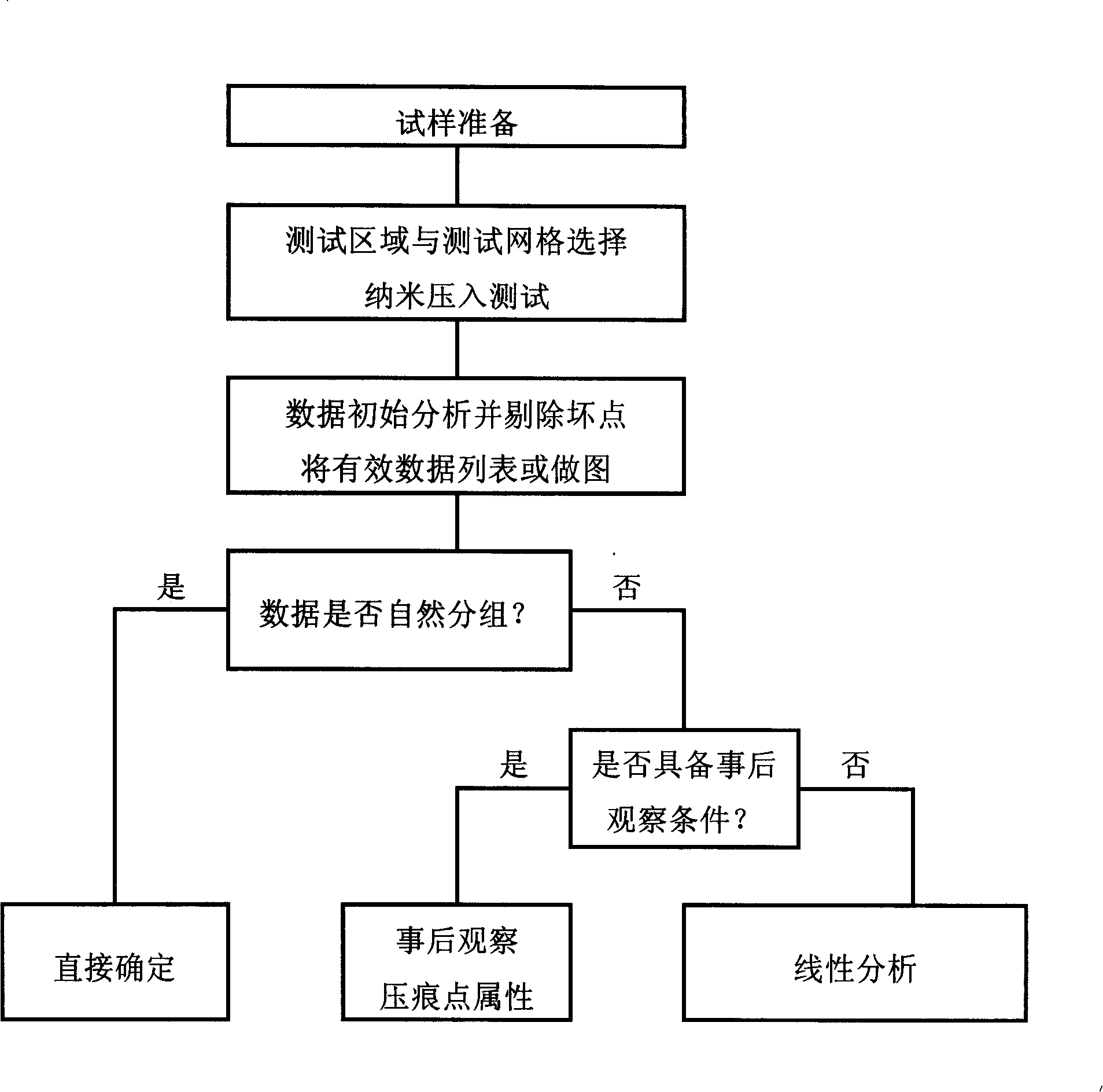
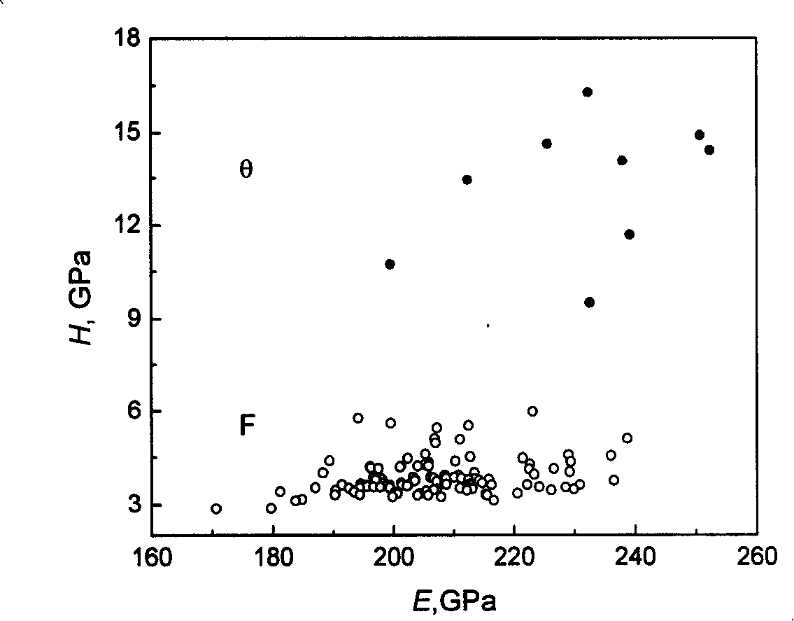
[0061] The specific scheme of the nanoindentation test is shown in Table 1. The obtained 119 effective data points are listed in Table 2 in order of hardness from high to low. It can be seen that the first 9 data points form a group of their own (in the thick line box in the upper left corner of the table), and their hardness is obviously higher than that of the rest of the data points. If the above 119 effective data are plotted in the plane Cartesian coordinate system, we can get the following image 3 E-H scatter plot shown. From this, it can be seen more intuitively that there are indeed 9 data points forming a group by themselves (the upper part of the figure), and their hardness is obviou...
Embodiment 2
[0069] The multiphase material to be tested is ferritic-austenitic duplex stainless steel in as-cast state, and its microstructure is as follows: Figure 4 As shown, there are coarse dendritic austenite phases (A) distributed in the matrix ferrite phase (F).
[0070] The specific scheme of the nanoindentation test is shown in Table 1, and the scatter diagram of the 228 effective data points obtained in the test is shown in Table 1. Figure 5 . It can be seen that these data points are not grouped naturally, but because the steel is cast, the dendrites are very thick (see Figure 4 ). This can easily be determined one by one by light microscopy (“after the fact”) after the press-fit test Figure 6 The constituent phases corresponding to each indentation point in the Figure 5 The constituent phases corresponding to each data point in , the final result of the judgment is shown in Figure 7 . due to m min =82>5, the aforementioned nanoindentation test scheme (see Table 1)...
Embodiment 3
[0071] Embodiment 3 (the linear analysis result of embodiment 2):
[0072] Since the data points do not have natural groupings, Example 2 uses hindsight ( Figure 6 ) to determine the correspondence between the data points and the constituent phases ( Figure 7 ). analyze Figure 7 , if a straight line is drawn in the figure to divide the data points into two groups, most of the data points on the left side of the dividing line correspond to the austenite phase (A), and most of the data points on the right side correspond to the ferrite phase ( F). This means that the linear analysis method can be used to approximate the correspondence between the data points and the constituent phases without the condition of "observation after the fact". When solving the boundary equation shown in formula (1), it is necessary to ensure that the total number of misjudged data points (that is, the wrong correspondence between data points and composition phases) is the least. Thus, determi...
PUM
| Property | Measurement | Unit |
|---|---|---|
| diameter | aaaaa | aaaaa |
Abstract
Description
Claims
Application Information
 - R&D
- Intellectual Property
- Life Sciences
- Materials
- Tech Scout
- Unparalleled Data Quality
- Higher Quality Content
- 60% Fewer Hallucinations
Browse by: Latest US Patents, China's latest patents, Technical Efficacy Thesaurus, Application Domain, Technology Topic, Popular Technical Reports.
© 2025 PatSnap. All rights reserved.Legal|Privacy policy|Modern Slavery Act Transparency Statement|Sitemap|About US| Contact US: help@patsnap.com


