Vehicle driving device

A driving device and vehicle technology, applied in the direction of power devices, transmission devices, electric power devices, etc., can solve problems such as difficult installation space

Inactive Publication Date: 2008-07-30
AISIN AW CO LTD
View PDF1 Cites 6 Cited by
  • Summary
  • Abstract
  • Description
  • Claims
  • Application Information

AI Technical Summary

Problems solved by technology

Therefore, for example, when the transmission mechanism 57 is multi-shifted to require complex hydraulic contro...

Method used


Image

  • Vehicle driving device
  • Vehicle driving device
  • Vehicle driving device

Examples


Embodiment Construction

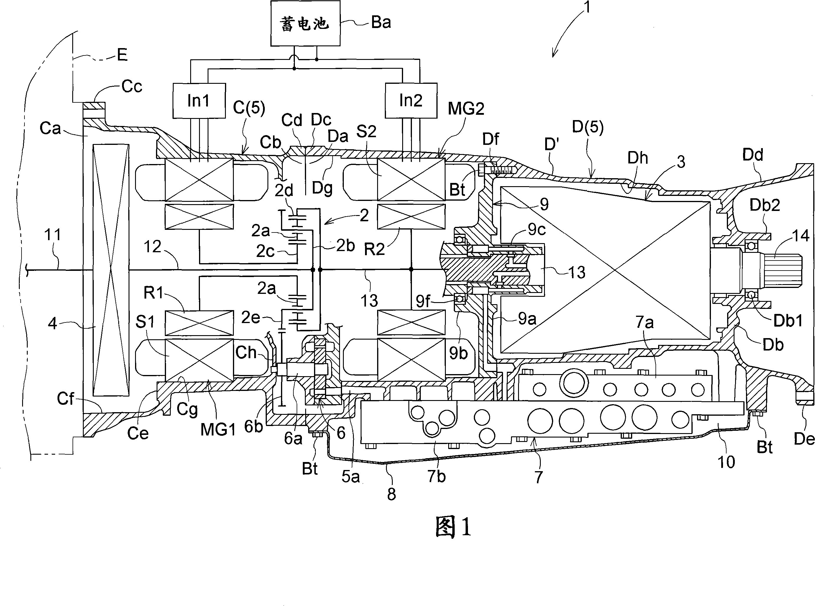
[0034] Embodiments of the present invention will be described below with reference to the drawings. In the present embodiment, a case will be described in which the vehicle drive device 1 receives driving force from the engine E and includes two motor / generators MG1 and MG2 as electric motors as an example.

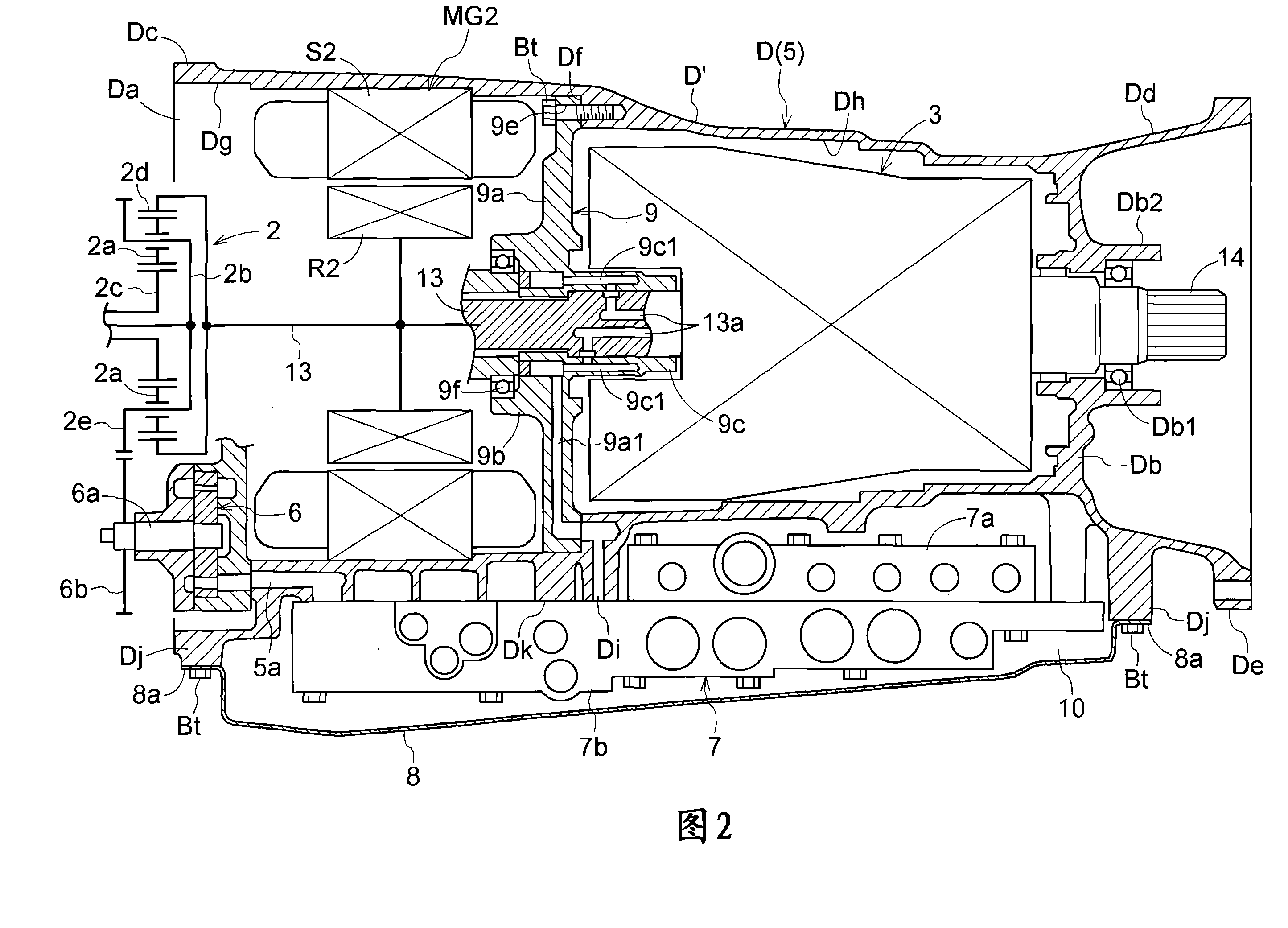
[0035] FIG. 1 is a cross-sectional view showing the overall configuration of a vehicle drive device 1 according to the present embodiment. In addition, FIG. 2 is an enlarged view of a main part of FIG. 1 . In these figures, the first motor / generator MG1, the second motor / generator MG2, the power split mechanism 2, and the transmission mechanism 3 are schematically shown. In addition, the engine E, the battery Ba, and the inverters In1 and In2 connected to the vehicle drive device 1 are also schematically shown.

[0036] 1. Overall composition

[0037] As shown in FIG. 1 , the vehicle drive device 1 is mainly configured to include a first motor / generator MG1 , a second ...


PUM


Abstract

The present invention provides a vehicle drive device capable of ensuring sufficient installation space for a hydraulic control device and a capacity of an oil pan. The drive device (1) for a vehicle is configured by accommodating a speed change mechanism (3) and an electric motor (MG2) in a case (D), and disposing a hydraulic control device (7) on the outer wall of the case (D), wherein the case (D), there is an opening (Da) at one end of the case main body (D') into which the speed change mechanism (3) and the motor (MG2) can be inserted, and the other end side of the case main body (D') is connected to the case main body (D') integrally has the other end wall portion (Db) provided with a shaft support portion (Db1) for supporting the output shaft (14) of the speed change mechanism (3).

Description

technical field [0001] The present invention relates to a driving device for a vehicle, which is composed of a transmission mechanism having a frictional engagement mechanism controlled by hydraulic pressure and a motor housed in a casing, and a device for controlling the frictional engagement mechanism to the frictional engagement mechanism is arranged on the outer wall of the casing. A hydraulic control device that supplies hydraulic pressure to the mechanism. Background technique [0002] Regarding a vehicle drive device including a transmission mechanism and an electric motor, for example, Patent Document 1 below discloses a configuration as shown in FIG. 4 . This FIG. 4 shows a side sectional view of a vehicle drive device 51 described in Patent Document 1. As shown in FIG. This vehicle driving device 51 comprises a damper device 53, a first motor / generator 54, a power distribution mechanism 55 composed of a planetary gear mechanism, a second The motor / generator 56 an...

Claims


Application Information

Patent Timeline
IPC IPC(8): B60K6/44B60L11/14F16H57/02F16H61/00B60K6/26B60K6/365B60K6/40B60K6/405B60K6/445B60K6/547B60K17/04B60L15/00B60L50/16F16H57/021F16H57/023F16H57/025F16H57/04F16H61/68F16H61/684F16H61/686
CPCB60K1/02B60K6/365B60K6/40B60K6/405B60K6/445B60K6/547B60K2001/003F16H3/728F16H57/02F16H57/0441F16H2037/0873F16H2057/02013F16H2057/02034Y10S903/952F16H61/0009Y10T74/2186Y02T10/62
Inventor 糟谷悟鬼头昌士田端淳柿并拓马小嶋昌洋茨木隆次岩濑雄二
Owner AISIN AW CO LTD
Why Eureka
Try Eureka