Brake device or safety clamp for protecting temporary elevator safety space

A technology of braking device and safe space, applied in the direction of brake type, transportation and packaging, elevator, etc., it can solve the problems of complexity, safety gear device cannot be re-released by remote control, and cannot ensure uniform pressure on the guide rail, etc., so as to reduce wear and tear. Effect

Active Publication Date: 2008-07-30
WITTUR
View PDF1 Cites 3 Cited by
  • Summary
  • Abstract
  • Description
  • Claims
  • Application Information

AI Technical Summary

Problems solved by technology

This known safety gear device is more complex than the ones described above, which generally do not guarantee uniform pressing on the guide rails and cannot be operated remotely, at least as far as the brake

Method used


Image

  • Brake device or safety clamp for protecting temporary elevator safety space
  • Brake device or safety clamp for protecting temporary elevator safety space
  • Brake device or safety clamp for protecting temporary elevator safety space

Examples


Embodiment Construction

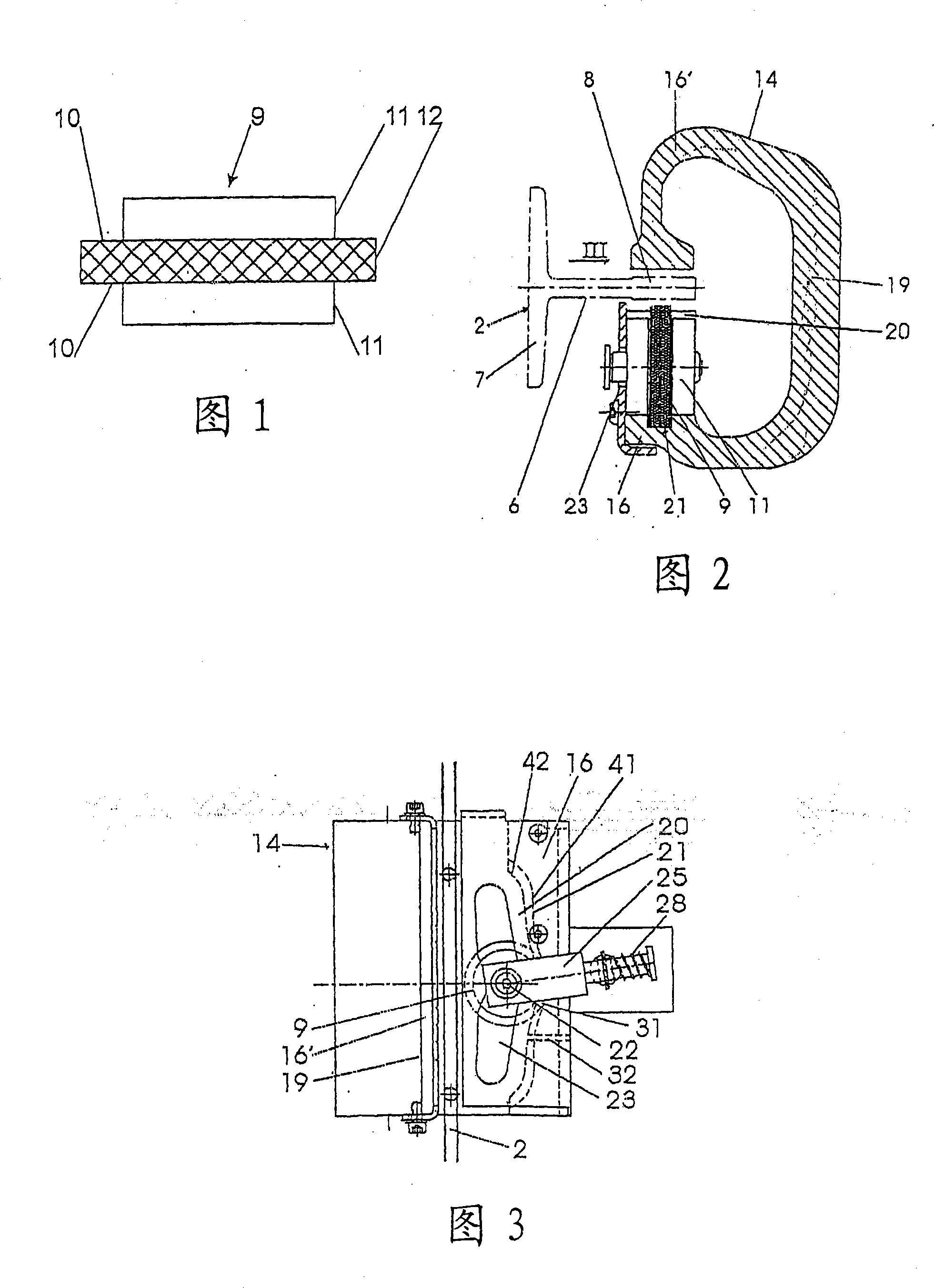
[0045] As shown in FIG. 2 , the guide rail 2 has a rail head 8 connected to the rail foot via a web 6 .

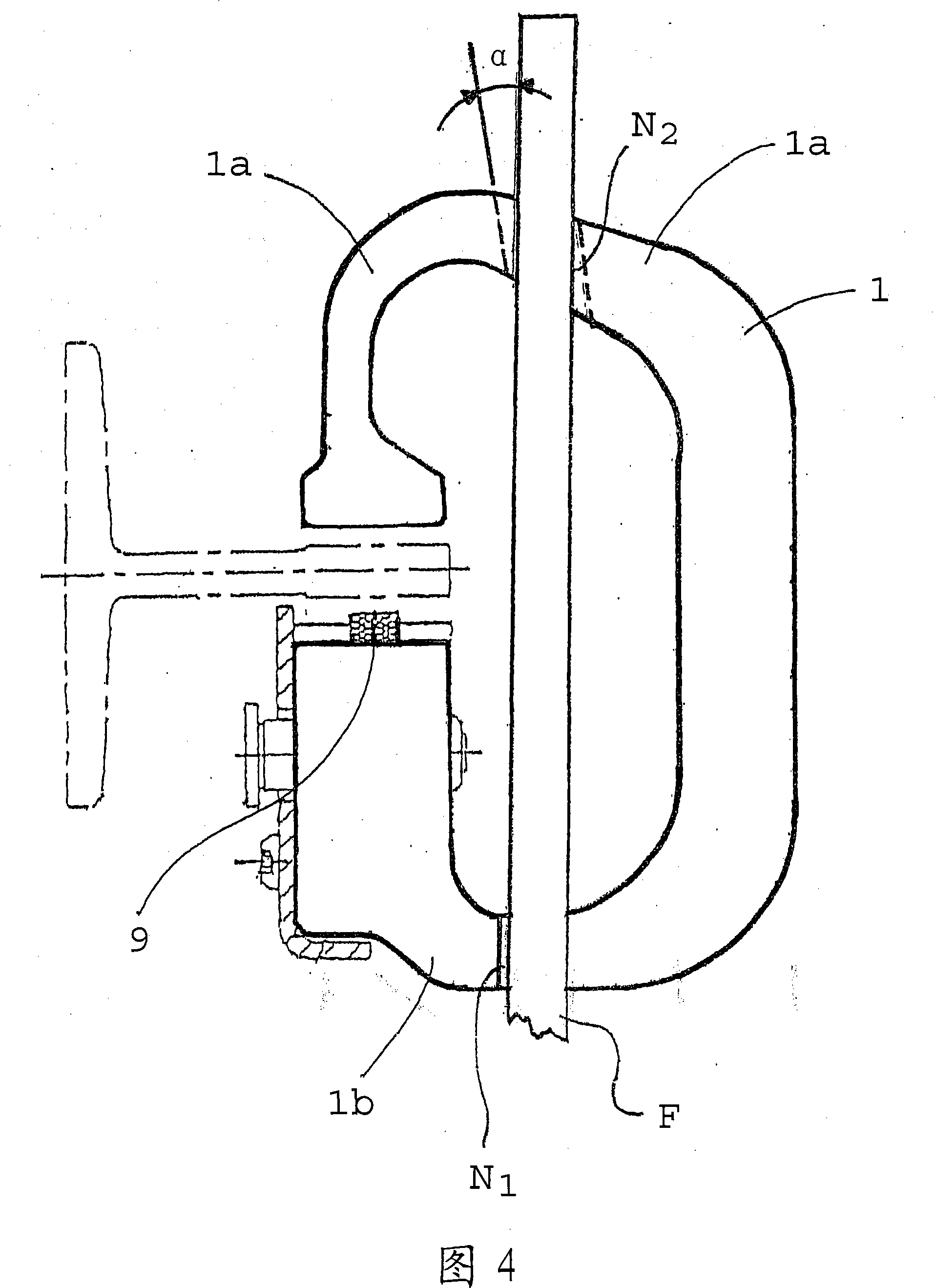
[0046] In the braking device or safety gear according to the invention, a braking mechanism in the form of a roller 9 is provided which is provided with shoulders 11 on its end faces 10 (see FIG. 1 ). The outer peripheral surfaces of the rollers 9 function as friction surfaces 12 . For this purpose, the rollers have knurls or friction layers, which are used to make contact with the guide rail (see FIG. 2 ).

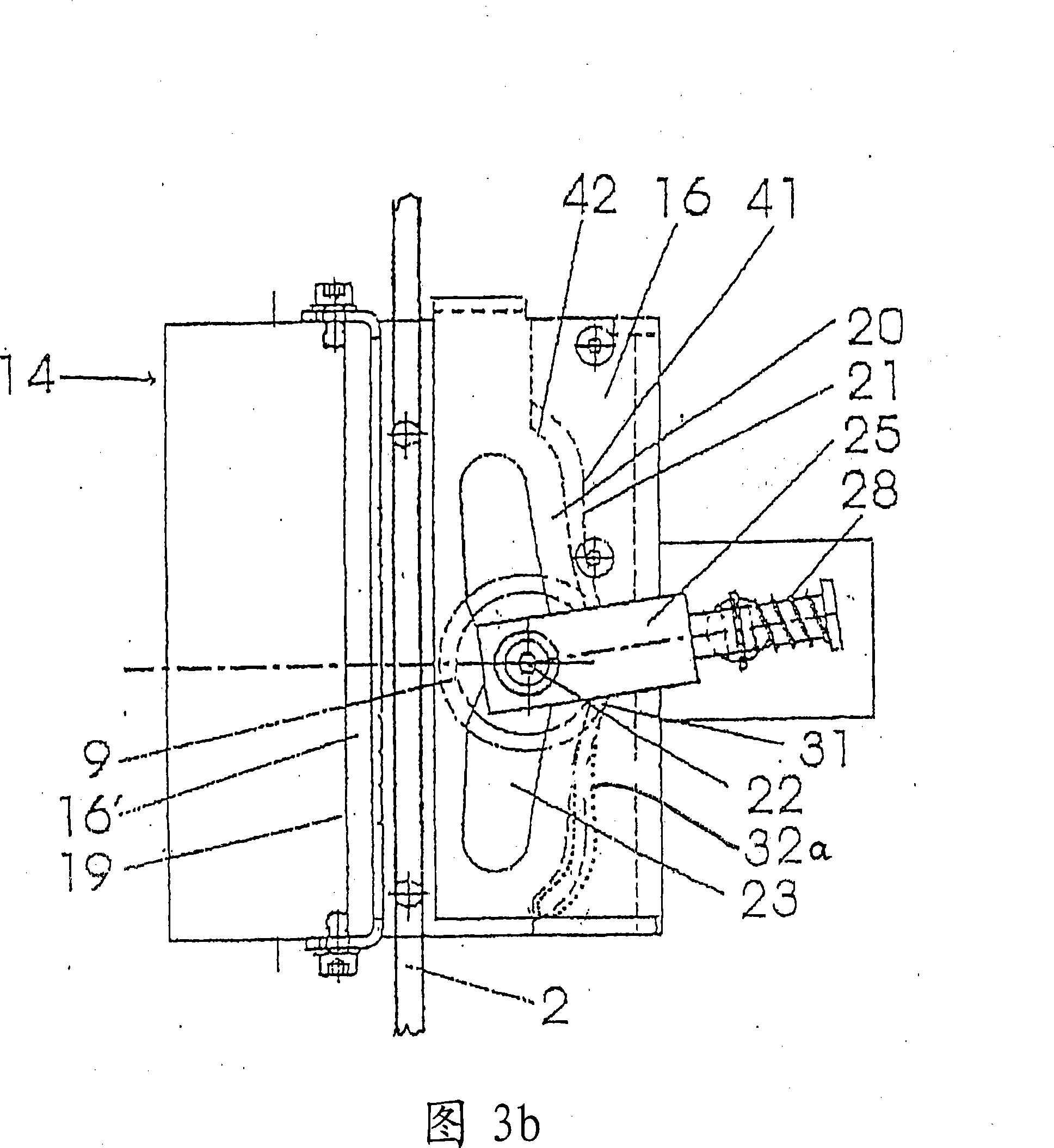
[0047] FIG. 2 shows the brake device 14 according to the invention in horizontal section. The braking device 14 has a caliper body 19, which is essentially a U-shaped profile, and the two legs 16, 16' have guide rails 2 in the region of their free ends. On the legs 16 of the pliers body 19 there are slots 20 in which the rollers 9 run. Furthermore, the slot 20 has a groove 21 which can accommodate the friction surface 12 of the roller 9 (see FIG. 1 ). The body of ...


PUM


Abstract

The invention relates to a braking or holding device for a lift cage which is guided in a shaft along vertical guiding rails (2). A roller (9) provided with a friction surface (12) on the envelope surface thereof is movably held, as a braking element, in a pressure body (19) of the braking device, held on the lift cage. The axis of the roller (9) extends normally to the longitudinal direction of the guiding rails (2). The roller is movably guided, by staggered shoulders (11), in a gap (20) of the pressure body, which extends parallel to the associated guiding rail (2), said gap (20) comprising a groove (21) for receiving the friction surface (12) of the roller (9). The distance between the groove (21) and the guiding rail (2) narrows towards one end of the groove, such that the friction surface (12) of the roller (9) lies on the guiding rail (2) in this position and in the groove (21) in position (41). Furthermore, in this position, the shoulders of the roll (9) lie on the gap (20) near the groove (21), in position (41), such that further displacement of the roller (9) is prevented. The gap (20) and the groove (21) extend from a recess (31) defining the inactive idle position, towards both sides, and the roller (9) is connected to an actuator which defines the inactive idle position of the roller and can be remote-controlled by a lift control system, said actuator being embodied in such a way that it subjects the roller to actuating forces oriented substantially perpendicularly to the guiding rail, and thus holds the roller (9) in the recess defining the inactive idle position thereof, as long as the braking or holding device remains passive, and as soon as the braking or holding device is active, the actuator is, in turn, controlled by the lift control system, moving the roller out of the idle position towards the guiding rail and bringing it into contact with same. The groove (21) and the gap (20) are formed, over the regions in which they exert a gripping or friction action on the shoulders (11) or the gripping surface (12) of the roller (9), in the activated state of the braking or holding device, in such a way that the roller (9), following the reversal of the direction of displacement of the lift cage, moves autonomously back into a position wherein it can be brought back into the inactive idle position thereof by the return forces of the actuator controlled by the lift control system, and the actuator is embodied in such a way that it brings the roller from this position into the recess defining the inactive idle position thereof, before the roller is pulled into the opposite groove or gap and thereby brakes in the opposite direction.

Description

technical field [0001] The invention relates to a braking device or safety gear for an elevator car which runs along vertical guide rails in a hoistway, where the braking device or safety gear operates a roller equipped with a friction surface and acting as a body of the tongs , the roller is friction-guided in a slot running obliquely relative to the guide rail and is elastically pressed against the guide rail in order to exert a corresponding friction there. The invention also relates to the use of such a braking device or safety gear. The term "elevator car" is used here and in the following as a generic term which includes not only the common assembly of all types of cars or slabs and carried by car frames, but also structures without car frames. Background technique [0002] The braking device or safety gear of the elevator is used to brake the elevator car when the speed of the elevator car is higher than the permissible limit, as can occur in the event of a controlle...

Claims


Application Information

Patent Timeline
IPC IPC(8): B66B5/22F16D63/00
CPCF16D63/008
Inventor 沃尔夫冈·阿德丁格马库斯·埃尔恩德勒于尔根·卡纳
Owner WITTUR
Why Eureka
Try Eureka