Spiral hole milling device

A helical milling hole and screw technology, applied in the direction of feeding device, milling machine equipment, milling machine equipment details, etc., can solve the problems of large eccentricity adjustment error, difficult adjustment of radial offset device, poor rigidity of radial offset device, etc. , to achieve the effect of large friction force surface, good structure holding function and small deformation

Active Publication Date: 2014-10-29
DALIAN JIAOTONG UNIVERSITY
View PDF10 Cites 21 Cited by
  • Summary
  • Abstract
  • Description
  • Claims
  • Application Information

AI Technical Summary

Problems solved by technology

[0006] Aiming at the technical problems of large eccentricity adjustment error, no clamping device, poor rigidity of radial offset device and radial offset device will be more difficult to adjust as the eccentricity increases in the structure proposed by the above patent, the present invention provides a A helical milling device with high adjustment precision, good working stability and convenient adjustment

Method used


Image

  • Spiral hole milling device
  • Spiral hole milling device
  • Spiral hole milling device

Examples


Embodiment Construction

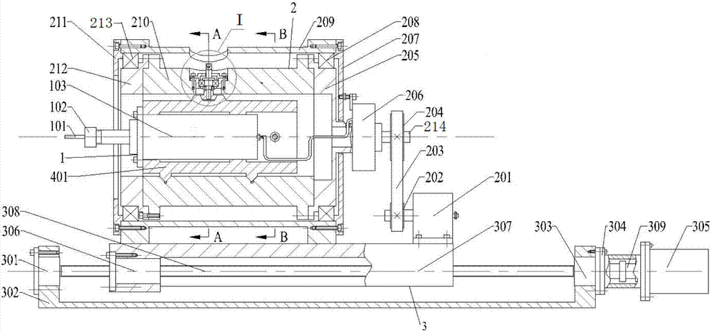
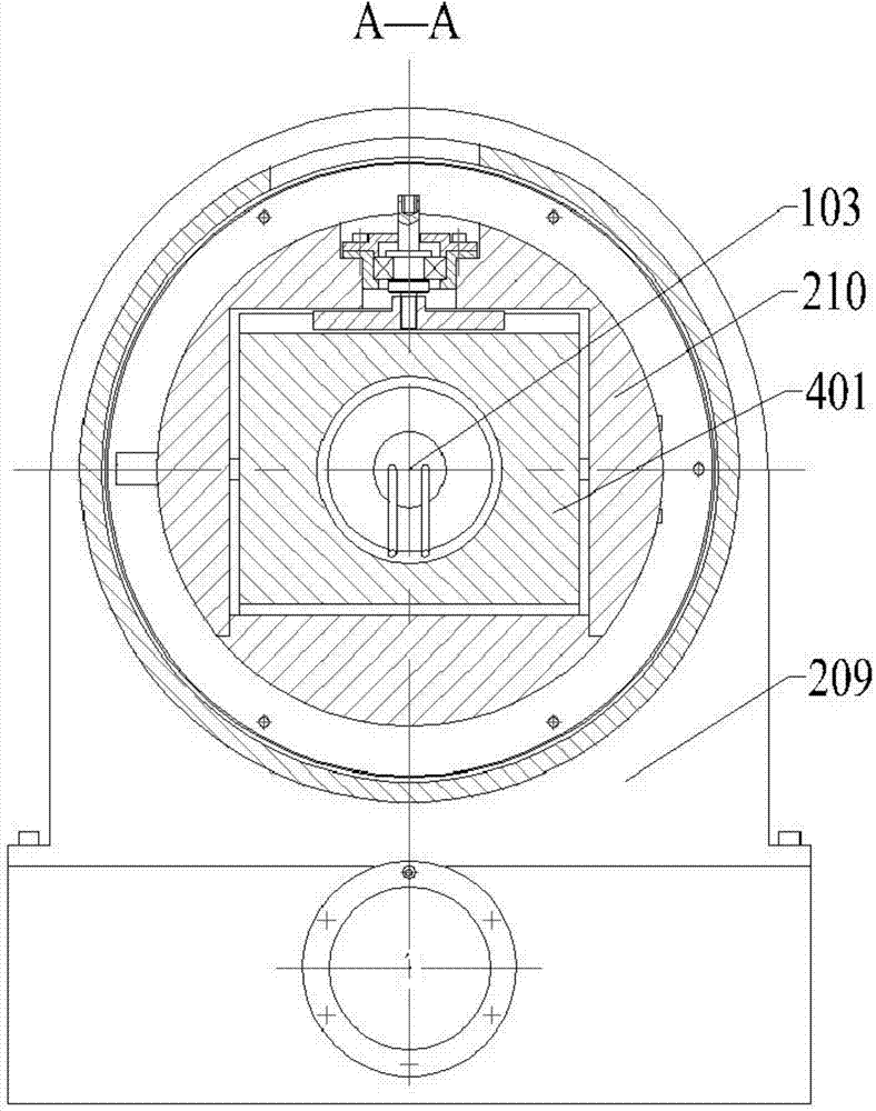
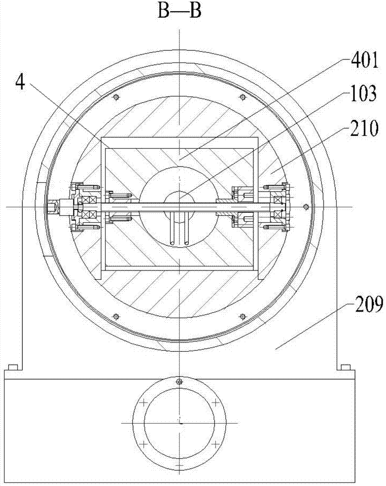
[0044] Such as Figure 1-Figure 5 As shown, a helical milling device includes an autorotation system 1, a revolution system 2, a feed system 3 and an eccentricity adjustment system 4 that drive the tool movement;

[0045] The autorotation system 1 is movably connected with the inner sleeve 210 through the offset slider 401, the autorotation system 1 includes a milling cutter 101, a collet 102 and an electric spindle 103, and the milling cutter 101 passes through the The collet 102 is fixedly connected to the output shaft of the electric spindle 103 .

[0046] The revolution system 2 includes a revolution motor 201, a small synchronous pulley 202, a synchronous belt 203, a large synchronous pulley 204, an inner sleeve rear end cover 205, a conductive slip ring 206, an outer sleeve rear end cover 207, and a radial bearing 208, outer sleeve 209, inner sleeve 210, outer sleeve front end cover 211 and inner sleeve front end cover 212, the outer sleeve 209 is fixedly connected to t...


PUM


Abstract

The invention discloses a spiral hole milling device. The spiral hole milling device comprises an rotationsystem, a revolution system, a feeding system and an eccentricity adjusting system. An electric main shaft in the rotation system drives a milling cutter to rotate through a spring collet arranged on an output shaft of the electric main shaft. A revolution motor in the revolution system drives an inner sleeve to perform revolution relative to the axis of an outer sleeve through a small synchronous pulley, a synchronous belt and a large synchronous pulley. A feeding motor in the feeding system drives a feeding lead screw to enable a feeding nut to move so as to achieve feeding. An eccentricity adjusting mechanism in the eccentricity adjusting system controls motion of a shifting sliding block, a fixed anti-backlash nut and a movable anti-backlash nut remove the backlash of the eccentricity adjusting system, and therefore high-precision adjustment of the eccentricity can be achieved. A holding mechanism arranged on the inner sleeve achieves the aim that the shifting sliding block is held on the inner sleeve after the eccentricity adjustment is completed. The spiral hole milling device can be applied to integral, high-quality and high-efficiency hole forming of difficultly-machined materials in the aerospace field.

Description

technical field [0001] The invention relates to the field of helical milling hole devices, which can be applied to the integrated, high-quality and high-efficiency hole making of difficult-to-machine materials in the aerospace field. Background technique [0002] At present, my country is in a period of rapid development of manufacturing technology, and cutting processing is the main basic process of manufacturing technology. As an important part of the manufacturing industry, aerospace has always been the industry with the richest high-tech. In aviation manufacturing, assembly hole making is a key link in the manufacture and assembly of aircraft and large aircraft. The hole making efficiency directly restricts the aircraft assembly cycle, and the hole making quality will also directly affect the fatigue resistance of the connected structural parts. The traditional drilling process is a continuous cutting process. For titanium alloys with poor thermal conductivity, the dril...

Claims


Application Information

Patent Timeline
Patent Type & Authority Applications(China)
IPC IPC(8): B23C3/00B23C9/00B23Q5/40
Inventor 张生芳马付建吴頔宿崇沙智华黄文丽
Owner DALIAN JIAOTONG UNIVERSITY
Why Eureka
Try Eureka