Supercharge Your Innovation With Domain-Expert AI Agents!

Digital signal encoding and decoding device and method

一种编码装置、解码装置的技术,应用在数字数据的压缩编码和解码领域,能够解决没有ROM表等问题

Active Publication Date: 2008-07-30
PANASONIC CORP
View PDF3 Cites 9 Cited by
  • Summary
  • Abstract
  • Description
  • Claims
  • Application Information

AI Technical Summary

Problems solved by technology

[0018] The image encoding device disclosed in Patent Document 3 has no ROM table for quantization

Method used


Image

  • Digital signal encoding and decoding device and method
  • Digital signal encoding and decoding device and method
  • Digital signal encoding and decoding device and method

Examples


Embodiment 1

[0123]

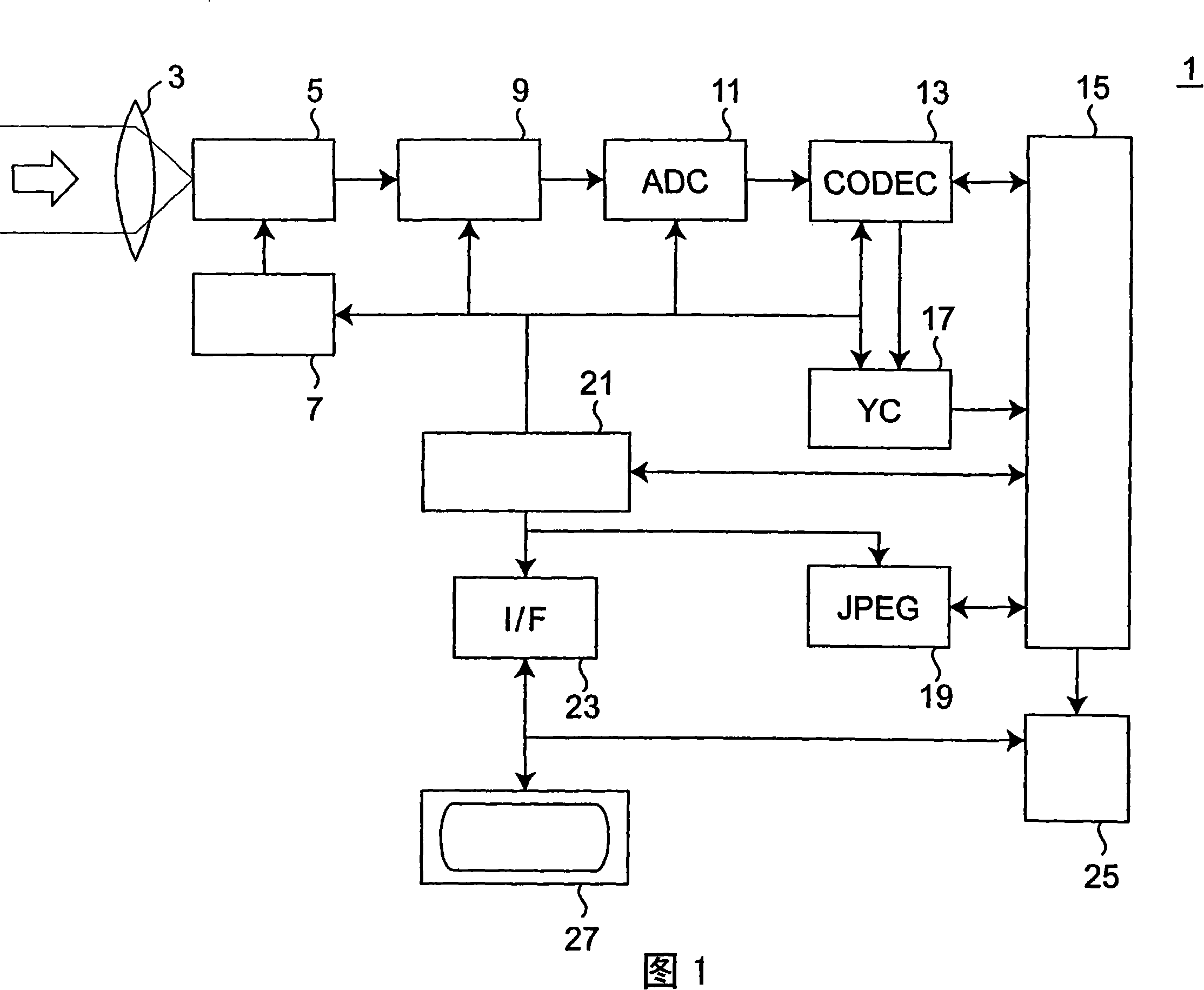
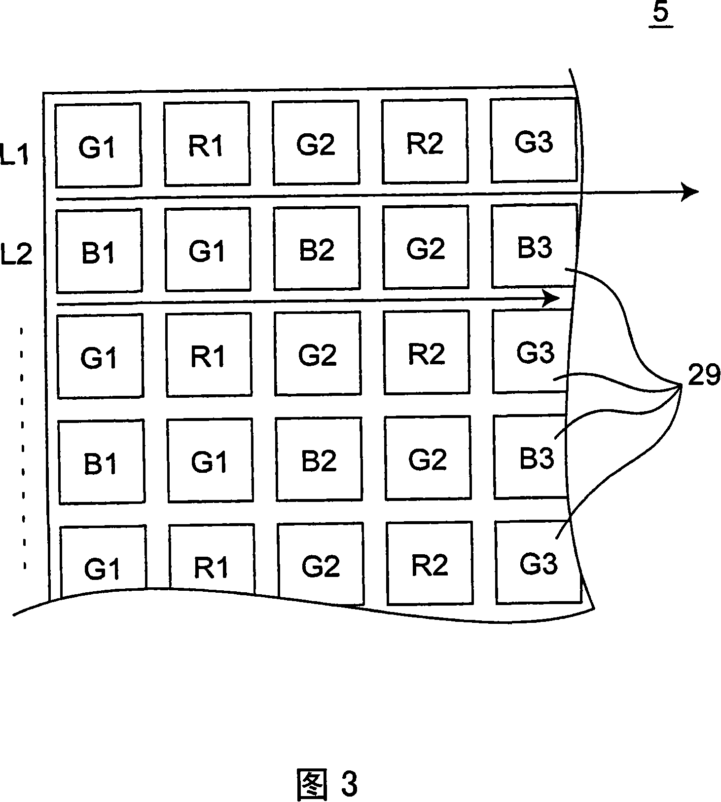
[0124] 1 is a block diagram of a digital still camera (DSC) 1 equipped with a digital signal compression encoding / decoding device (CODEC) 13 according to the present invention. Light incident to the lens 3 from an unillustrated object is condensed by the lens 3 and its image is formed in an unillustrated light receiving unit of the image pickup element 5 . The image pickup element 5 is a CCD type imaging element. The unillustrated pixels of the image pickup element 5 accumulate charges according to the amount of incident light. The image pickup element driving unit 7 outputs the accumulated charges as an analog pixel signal at predetermined timing, and sends the signal to the signal preprocessing unit 9 . The signal preprocessing unit 9 preprocesses the analog pixel signal, and sends the analog pixel signal to the analog / digital conversion unit 11 . An analog / digital conversion unit (ADC) 11 converts an analog pixel signal into a digital pixel signal, and outputs ...

Embodiment 2

[0220]

[0221] The present embodiment provides a digital still camera (DSC) provided with a CODEC having error feedback processing for reducing errors. This error (difference between pixel value data and decoded pixel value data obtained by applying compression encoding processing to pixel value data and further applying decoding processing to encoded pixel value data) often occurs in quantization of pixel value data by CODEC.

[0222] The DSC of this embodiment is the same as the DSC according to the first embodiment except for the processing performed by the CODEC 113 . According to FIG. 1, it can be considered that the CODEC 113 to be described below is installed on the DSC of this embodiment instead of the CODEC 13. Here, the configuration and processing of the CODEC 113 will be described. Portions not particularly described are the same as those of the first embodiment.

[0223] FIG. 9 is a block diagram of the CODEC 113 according to the present embodiment. The CODE...

Embodiment 3

[0234]

[0235] This embodiment provides a digital still camera (DSC) whose CODEC is capable of changing and optimizing the bit length (the number of bits of compression-coded pixel value data) of the compression-coded pixel value data according to the characteristics of the actually imaged object, the compression-coded pixel value data is the compressed encoded value of the pixel value data. This embodiment provides CODEC 213 with higher compression efficiency. The DSC of the present embodiment is the same as the DSCs of the first and second embodiments except for the processing in the CODEC 213 . According to FIG. 1, it can be considered that a CODEC 213 to be described below is mounted on the DSC of this embodiment instead of the CODEC 13. Here, the configuration and processing of the CODEC 213 will be described. Portions not particularly described may be the same as those in the first embodiment. The CODEC 213 of the present embodiment performs determination processin...


PUM


Abstract

An encoding device includes: a difference generation unit for obtaining a first pixel difference value as a difference value between a first pixel value and a pixel value of a pixel having the same color as the first pixel positioned in the vicinity of the first pixel; a quantization width decision unit for deciding a quantization width in data generation by quantizing the first and the second pixel value according to the number of digits of an unsigned integer binary value of the first pixel difference value and the number of digits of an unsigned integer binary value of the second pixel difference value generated in the difference generation unit for the second pixel value of the second pixel; a quantization width information generation unit for generating quantization width information having a quantization width used for quantization / decoding of the first and the second pixel value; and a quantization unit for generating a first and a second compressed encoded pixel value of n-bit length.

Description

technical field [0001] The present invention relates to compression encoding and decoding of digital data. More particularly, the present invention relates to an apparatus and method for compressing and encoding a pixel signal output from an image pickup element, and decoding the compressed and encoded pixel signal. Background technique [0002] Image pickup elements mounted on digital imaging devices such as digital cameras and cellular phones with built-in cameras include, for example, charge-coupled image pickup elements (CCD type image pickup elements) and metal oxide semiconductor type image pickup elements (MOS type image pickup element). Furthermore, the MOS type image pickup element includes a complementary metal oxide semiconductor type image pickup element (CMOS type image pickup element), an N-channel metal oxide semiconductor type image pickup element (NMOS type image pickup element), and the like. In recent years, the number of pixels of these image pickup ele...

Claims


Application Information

Patent Timeline
Patent Type & Authority Applications(China)
IPC IPC(8): H04N11/04H04N1/41H04N7/32H04N19/126G06T9/00H04N19/137H04N19/182H04N19/186H04N19/196H04N19/50H04N19/593
CPCH04N19/00303H04N19/00315H04N1/64H04N19/00096H04N1/41H04N19/00024H04N19/00569H04N19/105H04N19/50H04N19/126H04N19/186H04N19/182H04N19/124H04N11/04
Inventor 冈本和雄永石裕二重里达郎
Owner PANASONIC CORP
Features
  • R&D
  • Intellectual Property
  • Life Sciences
  • Materials
  • Tech Scout
  • Unparalleled Data Quality
  • Higher Quality Content
  • 60% Fewer Hallucinations
Learn More