Clamping fixture including a chuck and a workpiece pallet releasably located thereon

A technology for pallets and workpieces, which is applied to wood processing equipment, chucks, manufacturing tools, etc., and can solve problems such as limited tension transmission

Active Publication Date: 2008-08-06
EROWA
View PDF3 Cites 31 Cited by
  • Summary
  • Abstract
  • Description
  • Claims
  • Application Information

AI Technical Summary

Problems solved by technology

While on the one hand such clamping devices are able to handle relatively high compressive loads and transmit high torque and tilting moments, on the other hand the transmission of tension is limited for the reasons mentioned at the outset

Method used


Image

  • Clamping fixture including a chuck and a workpiece pallet releasably located thereon
  • Clamping fixture including a chuck and a workpiece pallet releasably located thereon
  • Clamping fixture including a chuck and a workpiece pallet releasably located thereon

Examples


Embodiment Construction

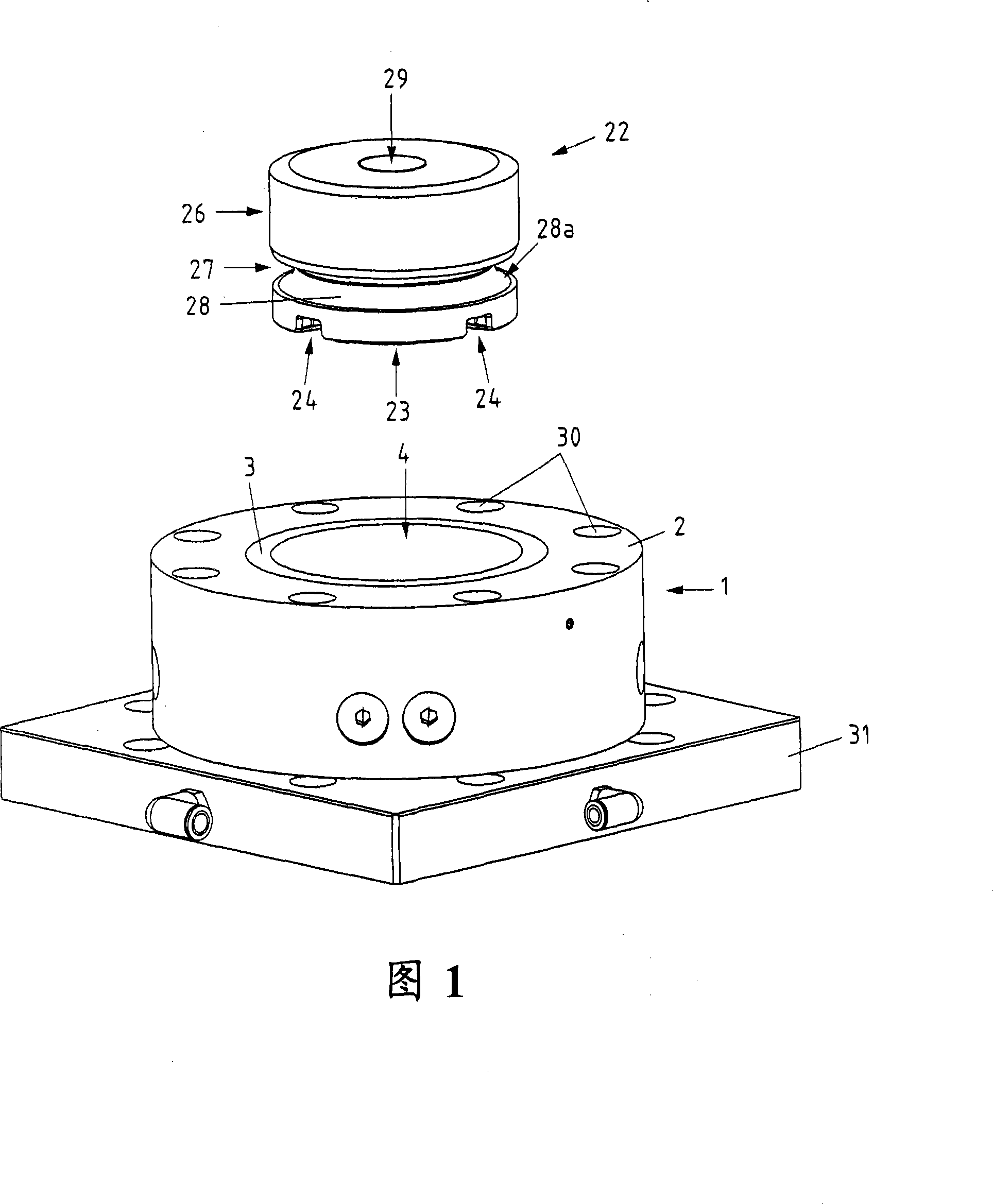
[0056] Referring to FIG. 1 , a perspective view of a holding device including a chuck 1 and a workpiece pallet 22 is shown. The chuck 1 is fastened to the base plate 31, but as far as possible the chuck 1 is fastened directly to the machine table. The workpiece pallet 22 is used to accommodate workpieces that are repeatedly positioned precisely on the chuck 1 . In the context of the present invention, however, the term workpiece pallet is by no means to be understood only for mounting workpieces, since tools and similar devices can also be fastened.

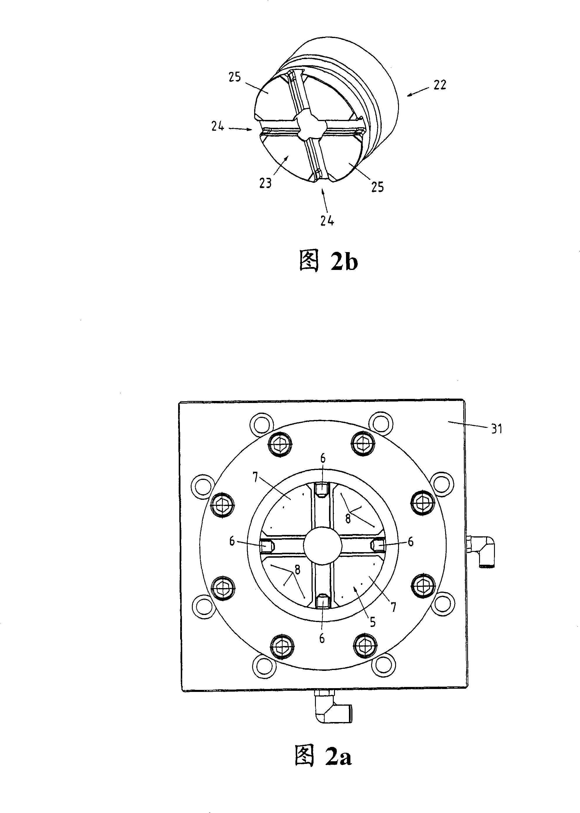
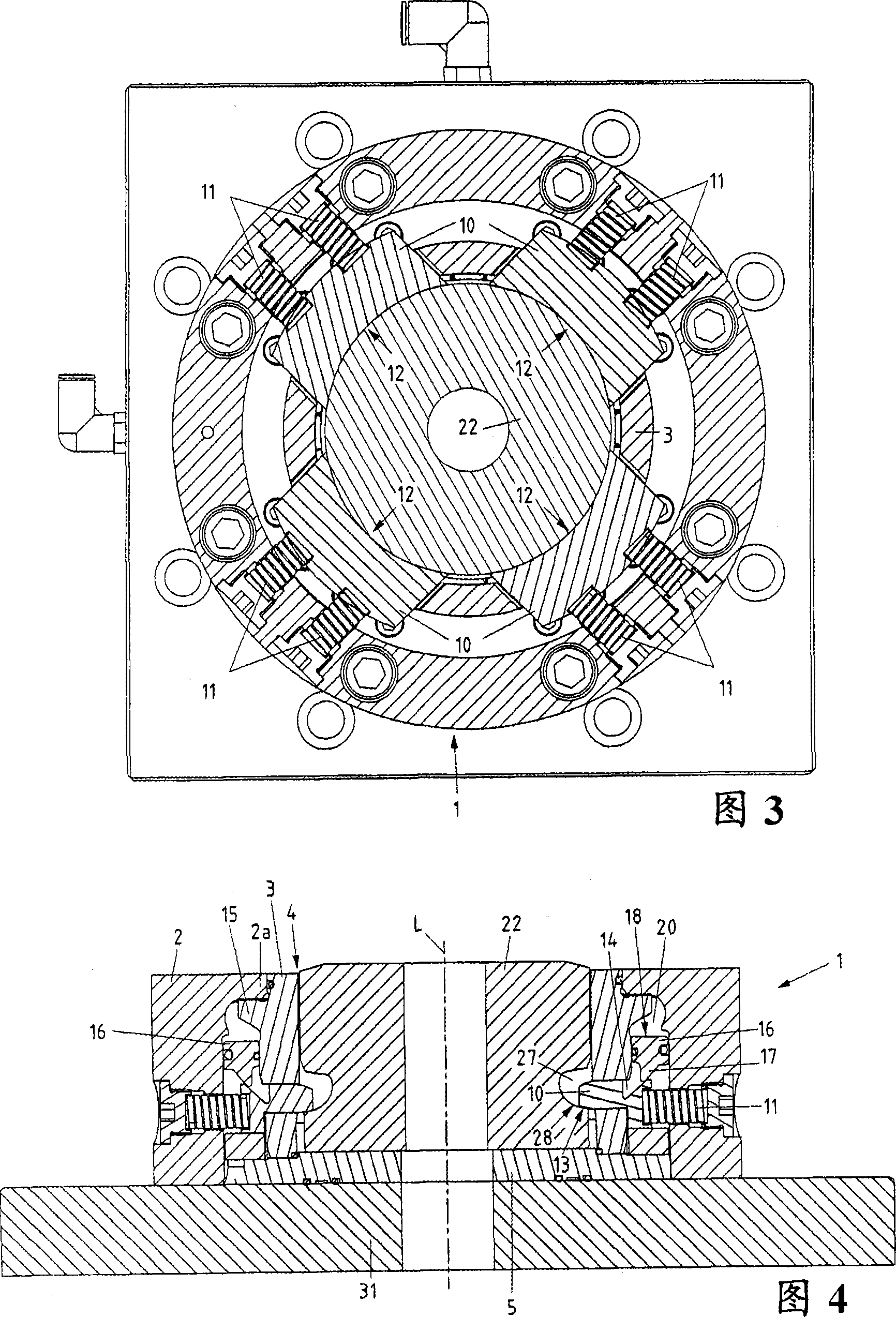
[0057]The chuck 1 comprises a cylindrical base 2 arranged along a bush 3 . The bushing 3 delimits a central opening 4 for receiving a workpiece pallet 22 and is configured substantially cylindrically. The flat bottom side 23 of the workpiece pallet 22 features a centering groove 24 for engaging a centering cam arranged on the chuck 1 when the workpiece pallet 22 is positioned on the chuck 1 . The complete fit of the centering ...


PUM


Abstract

A clamping device has a chuck (1) and a releasable workpiece support (22) in which the chuck (1) has a clamping mechanism for fixing the support (22). The clamping mechanism also has a number of clamping elements which are designed as sliding elements. The workpiece support (22) has a clamping surface (28a) extending along its lateral surface (26) on which the sliding elements are placed during tight clamping.

Description

technical field [0001] The invention relates to a holding device constructed as stated in the preamble of claim 1 . These holding devices are preferably used to hold a workpiece pallet (pallet) provided with a tool or a workpiece with a limited position. The chuck (chuck) is usually fixed on the table of the machine tool or press (press), and the The pallet is releasably positioned precisely on the chuck repeatedly. Background technique [0002] With known clamping implements, the pressure generated is mostly transmitted through the contact surfaces provided for this purpose and the overall tension has to be handled by the clamping mechanism provided with the clamping members. Such clamping mechanisms typically feature multiple spring-loaded clamping balls that engage a clamping column secured to the workpiece pallet when the workpiece pallet is clamped in place. Surface bonded or directly bonded to the workpiece pallet itself. While this type of gripper has proven to hav...

Claims


Application Information

Patent Timeline
Patent Type & Authority Applications(China)
IPC IPC(8): B23B31/02B23B31/107
CPCB23B2270/027B23B2260/126B23Q1/0072B23B2270/28B23B31/001B23B2270/12B23B31/1078B23B2270/025B23B31/30B27G13/10B27G13/12
Inventor B·桑德迈耶
Owner EROWA
Why Eureka
Try Eureka