All-sealing circulating cooling machine for clinker production

A circulating cooling and fully sealed technology, which is applied in the field of belt coolers or ring coolers, can solve the problems of cooling air leakage, sealing plate deformation, air leakage, etc., to facilitate the recovery and utilization of waste heat, increase the temperature of exhaust gas, and reduce the amount of exhaust gas Effect

Inactive Publication Date: 2008-08-06
QINHUANGDAO XINLV ENERGY SAVING TECH
View PDF0 Cites 11 Cited by
  • Summary
  • Abstract
  • Description
  • Claims
  • Application Information

AI Technical Summary

Problems solved by technology

At present, the exhaust gas of the belt cooler is generally directly discharged into the atmosphere. In order to improve the energy utilization rate, a waste heat recovery device is added on the belt cooler, and a cooling blower is installed at the lower end corresponding to it, so that the temperature with a temperature of 100°C-600°C can be reduced. Part of the exhaust gas is recycled; the other part is taken away by the exhaust gas discharged into the atmosphere; in addition, between the waste heat recovery device and the trolley; between the air supply bucket of the cooling blower and the trolley are all open structures, so that the The cooling air leaks through the open part, which is another cause of waste; in addition, due to the long-term operation of the cooler in a high-temperature, high-dust environment, the sealing plate and the fence inside the trolley fence have different degrees of damage. Deformation, thereby forming gaps, causing another air leakage problem; at the same time, the bottom of the trolley plate is constantly rubbing against the sealing plate on the bellows at high temperature, and a large number of gaps will also cause serious air leakage, resulting in an air leakage rate of over 50%.
Therefore, the problems of high energy consumption and high pollution in the cooling process of the current cooler have not been completely solved so far.

Method used


Image

  • All-sealing circulating cooling machine for clinker production
  • All-sealing circulating cooling machine for clinker production
  • All-sealing circulating cooling machine for clinker production

Examples


Embodiment Construction

[0013] The implementation and positive effects of the present invention are described in detail in conjunction with the accompanying drawings to help readers understand the essence of the present invention, and are not intended to limit the protection scope of the present invention.

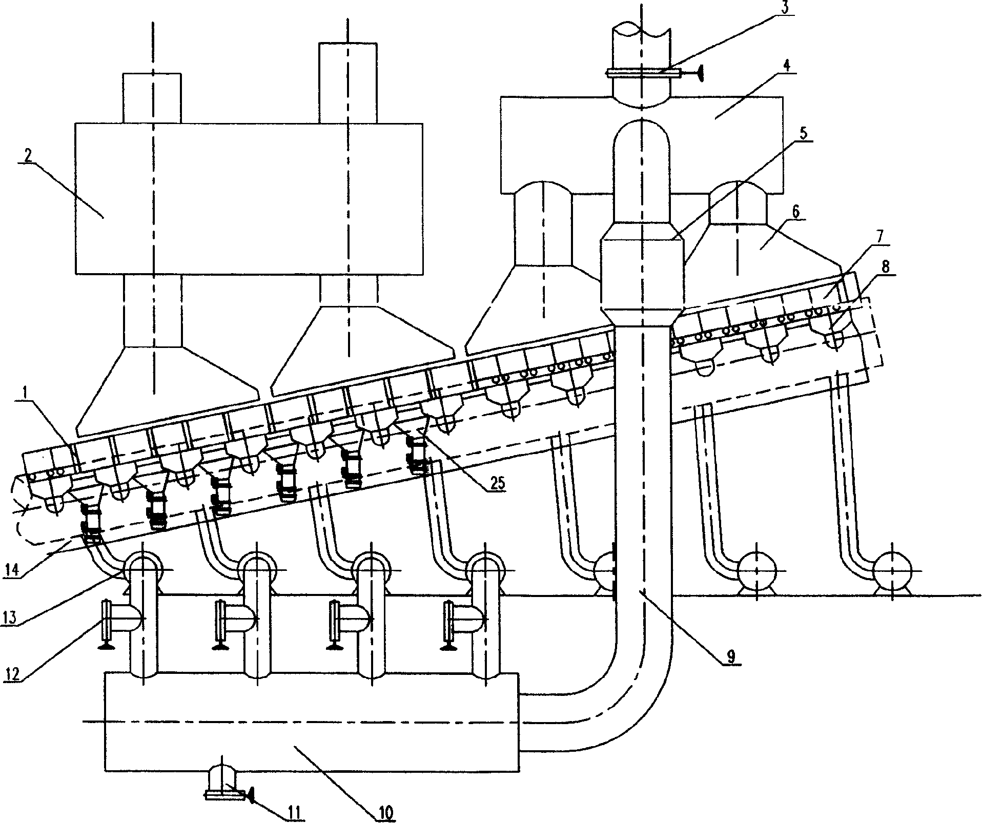
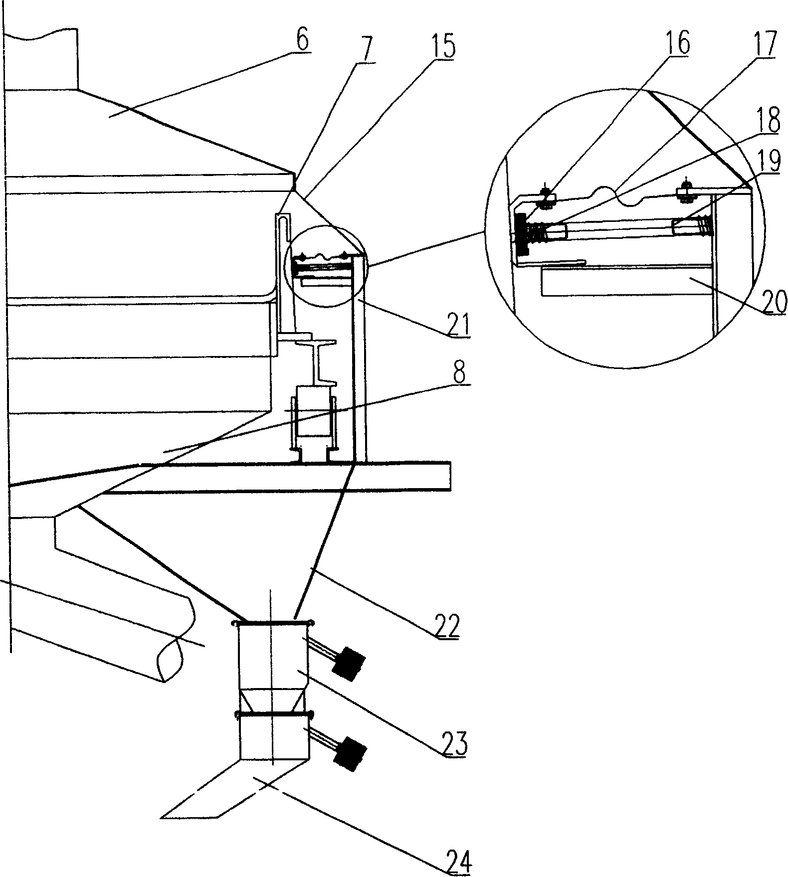
[0014] see figure 1 Shown, a kind of clinker production is used fully sealed circulation cooling machine, has a belt cooling machine 14 and trolley 7 that can move on it. The waste heat recovery device 2 is installed on the top of the trolley 7 above the belt cooler 14; the blower 13 corresponding to its lower end is used to solve the cooling waste gas utilization of the belt cooler. In order to increase the recycling of the heat source of the cooling exhaust gas, improve the recycling of the exhaust gas temperature and add an exhaust gas circulation recovery device to the dust collection hood 6 near the discharge end of the belt cooler 14; A waste gas collection box 4 is connected to the top, o...


PUM


Abstract

The invention provides fully sealed circulation cooler for clinker production, which comprises a belt cooler and sealing devices. A dust collector hood is arranged on the belt cooler, an air blower is arrange below the belt cooler, wherein a position, close to a discharging end of the belt cooler, on the dust collector hood is provided with waste gas collecting boxes mutually communicated, a waste gas distributor is connected to the waste gas collecting boxes by a recovery pipe line in series connection with a dust collector, a plurality of wind pipes are distributed on the waste gas distributor. The contacted and matched sealing devices are arranged between the belt cooler and a trolley. The fully sealed circulation cooler has the advantages that air leakage of the belt cooler is effectively resolved, recycling of waste gas heat source is realized, waste gas temperature is increased, residual heat is convenient in recycling and using, simultaneously influence, due to waste gas discharging in the air, on environment is reduced, and the fully sealed circulation cooler is used for belt or ring coolers in production of sintered ore, pellet ore or the solidified and agglomerated clinker by high-temperature reaction.

Description

technical field [0001] The invention relates to an improved structure of a fully sealed circulating cooler for clinker production, which is mainly suitable for belt coolers or ring coolers for the production of sintered ore, pellets, or clinker that is consolidated into blocks through high-temperature reactions , Improve energy utilization. Background technique [0002] In the production of sinter and pellets, the cooling process of sinter or pellets is one of the important processes, which provides a guarantee for the stable production of the next process. At present, the exhaust gas of the belt cooler is generally directly discharged into the atmosphere. In order to improve the energy utilization rate, a waste heat recovery device is added on the belt cooler, and a cooling blower is installed at the lower end corresponding to it, so that the temperature with a temperature of 100°C-600°C can be reduced. Part of the exhaust gas is recycled; the other part is taken away by t...

Claims


Application Information

Patent Timeline
Patent Type & Authority Applications(China)
IPC IPC(8): F27D9/00F27D17/00
Inventor 高彦胡建山孙美德
Owner QINHUANGDAO XINLV ENERGY SAVING TECH
Why Eureka
Try Eureka