
Three-dimensional scanners and its three-dimensional model reconfiguration method

A scanner and three-dimensional technology, applied in the field of three-dimensional scanning, can solve the problems of slow scanning speed, complicated operation, and inapplicability in the application field of three-dimensional scanning technology, so as to achieve strong applicability and improve the effect of stitching speed.

Inactive Publication Date: 2008-08-06
张利群 +1
View PDF0 Cites 33 Cited by
  • Summary
  • Abstract
  • Description
  • Claims
  • Application Information

AI Technical Summary

Problems solved by technology

[0004] For traditional 3D scanning equipment, most of them are contact scanners and laser scanners. The scanning speed is slow, the operation is complicated, and there are strict requirements for the tested parts and working conditions. They are not applicable in many application fields that require 3D scanning technology.
The recently developed raster 3D scanning technology is still in its infancy, and many technologies need to be perfected

Method used


Image

  • Three-dimensional scanners and its three-dimensional model reconfiguration method
  • Three-dimensional scanners and its three-dimensional model reconfiguration method
  • Three-dimensional scanners and its three-dimensional model reconfiguration method

Examples


Embodiment Construction

[0031] 1. Raster type 3D scanner

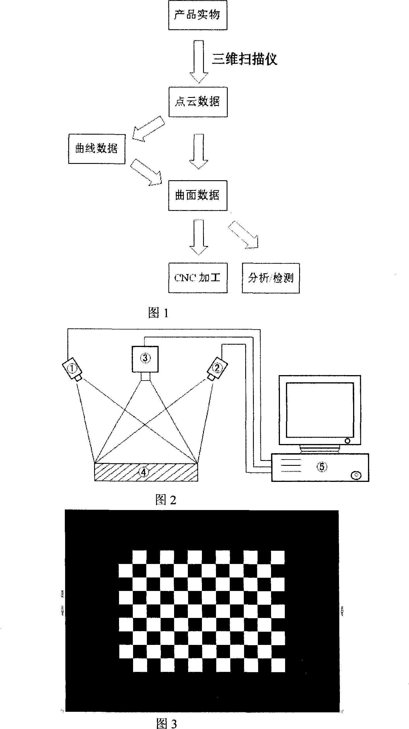
[0032] The system structure adopted in the present invention (as shown in Figure 2) is composed of grating generating equipment ③, image acquisition equipment ①②, calibration block ④, computer communication board ⑤ and peripheral mechanical support facilities. The grating generating device ③ is connected with the computer communication board ⑤, which is a light source device that can generate grating structured light, and its grating pattern can be changed by computer control. The image acquisition device ①② is connected with the computer communication board ⑤. Its main function is to collect the reflected image of the projected grating from the tested part. The number can be only one, or two to eight. The specific number depends on the system accuracy requirements. And it depends on the size of the object to be measured. Calibration block ④ (as shown in Figure 3) is a standard gauge block with strictly controlled dimensions and printed with...


PUM


Abstract

The present invention relates to a 3D scanner and a 3D model reconstructing method thereof, belonging to a metering device with the characteristic of adopting optical means and a metering method thereof in the 3D scanning field. The 3D scanner mentioned in the present invention belongs to a grating scanning device. The 3D scanner consists of an image acquisition device, a grating generation device, a calibration block, a computer communication card and a peripheral machinery supporting facility. The work flow and characteristics of the present invention are that: firstly the image acquisition device is calibrated; then reflected images produced by a tested object under the irradiation of different structured light patterns, so as to figure out the reflection point positions (point clouds) on the tested object and the positions of mark points stuck on the tested object; finally, an integral 3D model of the tested object is synthesized through the mutual matching relation between the point clouds and the mark points acquired every time. The present invention relates to a grating scanning device and puts forward a method of utilizing the device to splice repeatedly acquired data.

Description

technical field [0001] The invention belongs to a measuring device and a measuring method characterized by adopting an optical method in the field of three-dimensional scanning. [0002] The present invention mainly relates to the use of physical optical paths to generate optical patterns. After the optical collection equipment is calibrated, the optical collection equipment is used to collect images, the collected images are image-processed and the position of the tested part is calculated, and the results of multiple calculations are calculated. Splicing and other techniques. It can be used more effectively in industry, medical service industry and cultural industry. Background technique [0003] Three-dimensional scanning technology is widely used in industry, medical service industry and cultural industry. In industry, it is used for reverse engineering calculation, and for structure and shape measurement of workpieces with large volume, weak rigidity and complex shape....

Claims


Application Information

Patent Timeline
IPC IPC(8): G06T11/00G06T17/00
Inventor 张利群刘俊
Owner 张利群
Learn More