
Antenna assembly and digital TV receiver using the same

A technology for TV receivers and antenna components, which is applied to antenna parts, TVs, antennas, etc. It can solve the problems of many receiving dead spots, difficulty in receiving infrared signals by infrared receivers, and inconvenient use of remote controls, etc., to achieve strong receiving ability, Reduce the effect of receiving dead angle

Inactive Publication Date: 2008-08-06
FITILINK INTEGRATED TECH
View PDF1 Cites 1 Cited by
  • Summary
  • Abstract
  • Description
  • Claims
  • Application Information

AI Technical Summary

Problems solved by technology

If the modem is plugged into the USB interface behind the host computer or directly into the PCI slot inside the host computer, the infrared receiver set on the circuit board of the modem will be difficult to receive due to the obstruction of the host computer itself. Infrared signals sent by the remote control, resulting in more dead spots
Therefore, the use of the remote controller is very inconvenient, and it is possible that the digital TV receiver completely loses the remote control function

Method used


Image

  • Antenna assembly and digital TV receiver using the same
  • Antenna assembly and digital TV receiver using the same
  • Antenna assembly and digital TV receiver using the same

Examples


no. 1 example

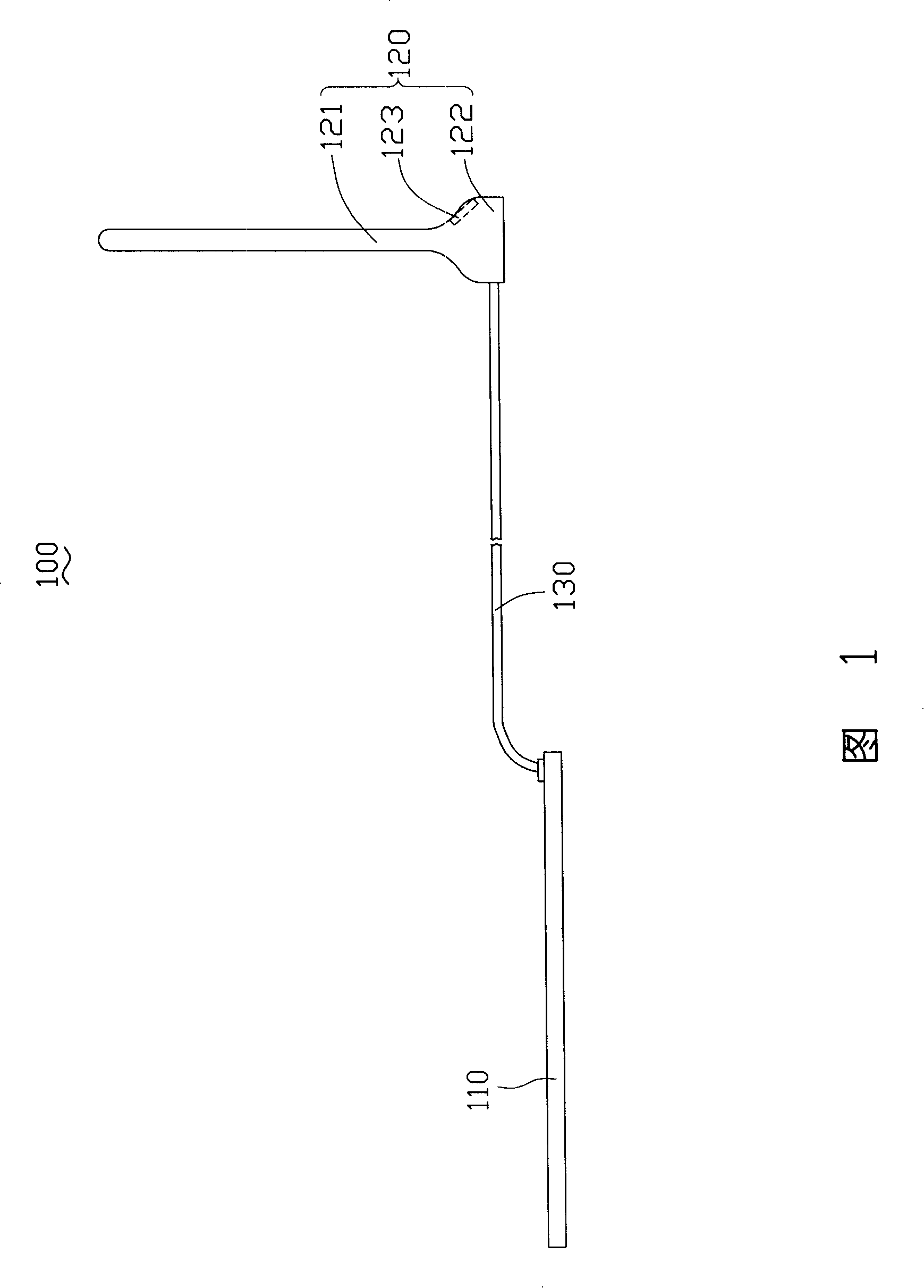
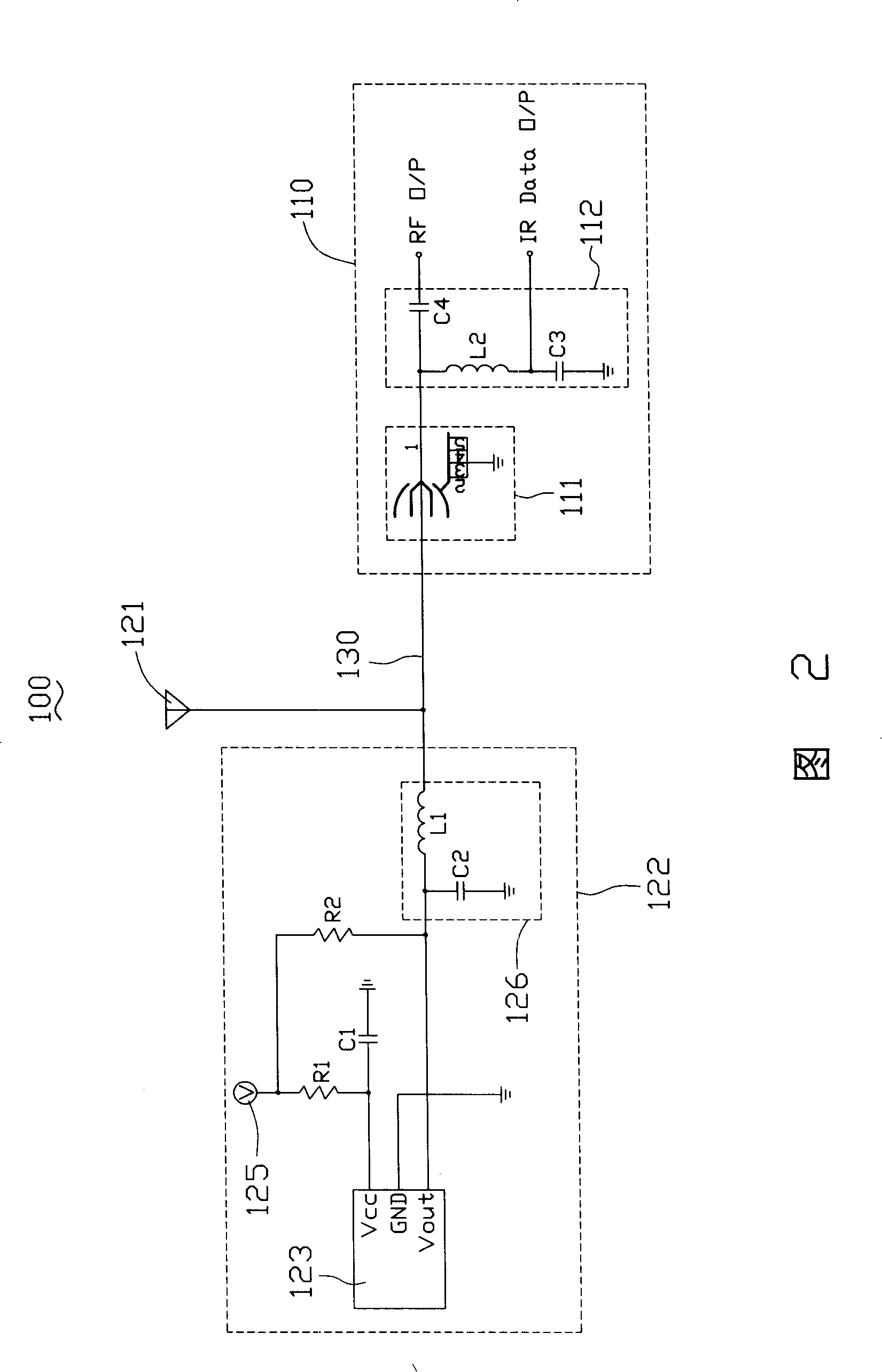
[0021] Please refer to FIG. 2 , which is a schematic diagram of circuit connections of the digital television receiver 100 provided by the first embodiment of the present invention. The antenna body 122 is provided with an independent voltage source 125 for supplying operating voltage to the infrared receiver 123 , that is, the voltage source 125 supplies operating voltage to the infrared receiver 123 , and does not supply operating voltage to the tuner 110 . The independently powered voltage source 125 can be a battery, or a power adapter (Power Adapter). Of course, it can be understood that the independently powered voltage source 125 can also be a power supply device in a computer, which supplies the infrared receiver 123 with an operating voltage through a transmission line. The output signal of the infrared receiver 123 is transmitted to the tuner 110 through the radio frequency cable 130 .

[0022] The independently powered voltage source 125 is electrically connected t...

no. 2 example

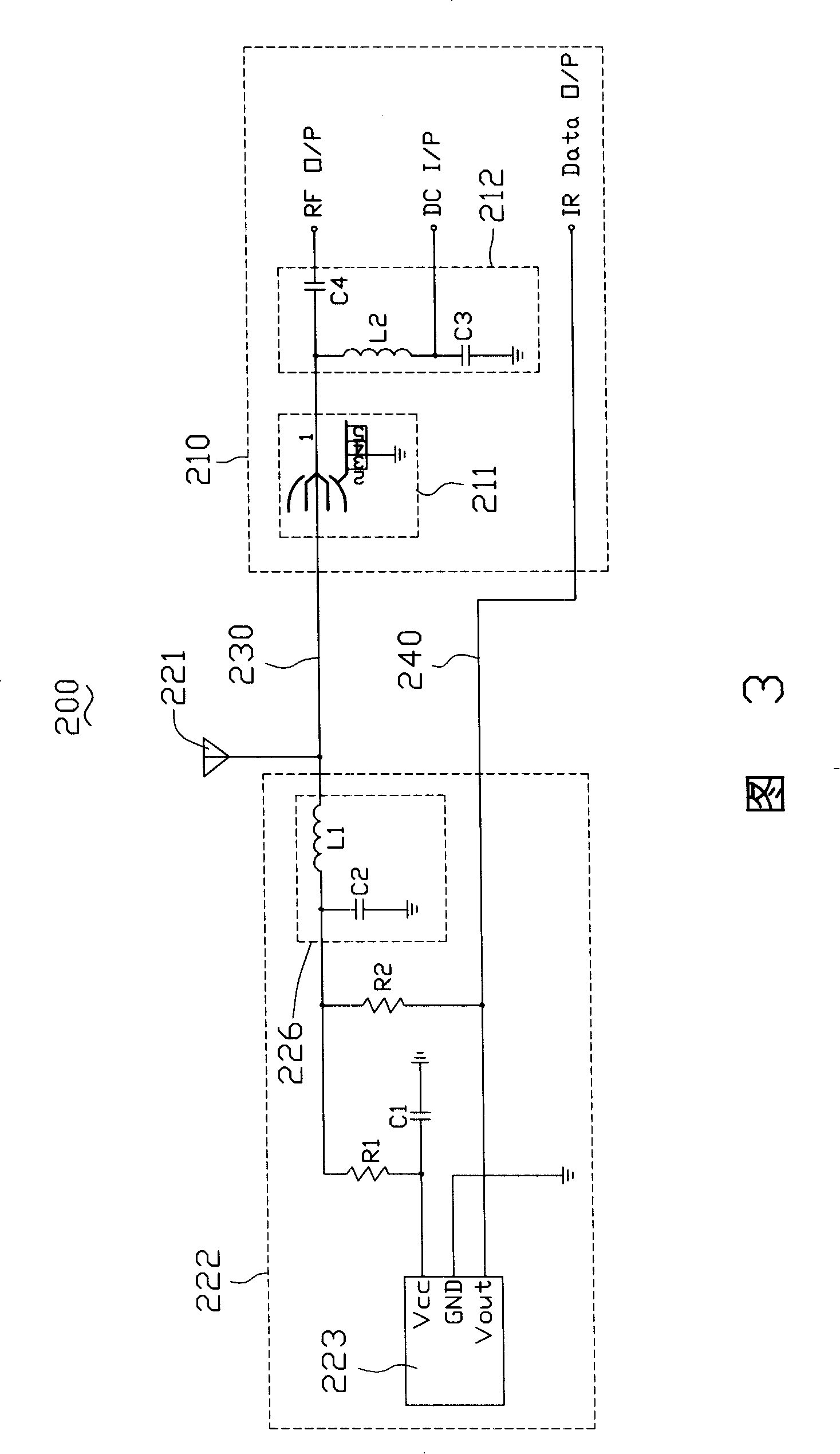
[0026] Please refer to FIG. 3 , which is a schematic diagram of circuit connections of the digital television receiver 200 provided by the second embodiment of the present invention. The circuit connection relationship provided by the second embodiment is substantially the same as that of the first embodiment, the difference is that there is no independent power supply voltage source inside the antenna body 222 , and the working voltage of the infrared receiver 223 is provided by the tuner 210 . The tuner 210 provides a DC working voltage to the infrared receiver 223 through the radio frequency cable 230 , and the output signal of the infrared receiver 223 is transmitted to the tuner 210 through a transmission line 240 .

[0027] Specifically, the node between the inductor L2 and the capacitor C3 in the second low-pass filter 212 in the tuner 210 is used as a DC voltage input port DC I / P, which can be electrically connected to the voltage source in the tuner 210, The voltage p...


PUM


Abstract

The present invention relates to an antenna component and a digital TV receiver adopting the antenna component. The antenna component comprises an antenna body and a receiving part extended from the antenna body, wherein, the antenna component also comprises an infrared receiver; the infrared receiver is arranged on the antenna body for receiving infrared signals sent from a remote controller. The antenna component ensure the digital TV receiver has strong capability of receiving signals sent from the remote controller.

Description

technical field [0001] The invention relates to an antenna assembly and a digital television receiver using the antenna assembly, in particular to an antenna assembly and a digital television receiver with a remote control receiving function. Background technique [0002] At present, computers are more and more popular, and their functions are more and more powerful, and it has become a trend to use computers to watch TV programs. And utilize computer to watch TV program and need a digital TV receiver to carry out the reception of TV signal, play the TV program received by the monitor of computer again. [0003] Existing digital TV receivers generally include a tuner (TV tuner) and an antenna assembly connected to the tuner. The antenna assembly is generally arranged in an open and obvious position, such as the top of the display, to receive TV signals and The received TV signal is transmitted to the tuner, and after certain signal processing, the received TV program is pla...

Claims


Application Information

Patent Timeline
Patent Type & Authority Applications(China)
IPC IPC(8): H01Q1/00H04N5/44H04N5/50
Inventor 杨文彬孔繁喜
Owner FITILINK INTEGRATED TECH
Learn More