An optical module receiving end performance testing device

A testing device and optical module technology, applied in the field of communication testing, can solve problems such as large testing errors, and achieve the effects of good signal receiving ability, weak receiving ability and strong receiving ability

Active Publication Date: 2021-04-13
武汉亿德光兴科技有限公司
View PDF5 Cites 0 Cited by
  • Summary
  • Abstract
  • Description
  • Claims
  • Application Information

AI Technical Summary

Problems solved by technology

[0003] The purpose of the present invention is to solve the shortcomings of large test errors in the prior art, and propose a performance test device for the receiving end of an optical module

Method used


Image

  • An optical module receiving end performance testing device
  • An optical module receiving end performance testing device

Examples


Embodiment Construction

[0018] The following will clearly and completely describe the technical solutions in the embodiments of the present invention with reference to the accompanying drawings in the embodiments of the present invention. Obviously, the described embodiments are only some, not all, embodiments of the present invention.

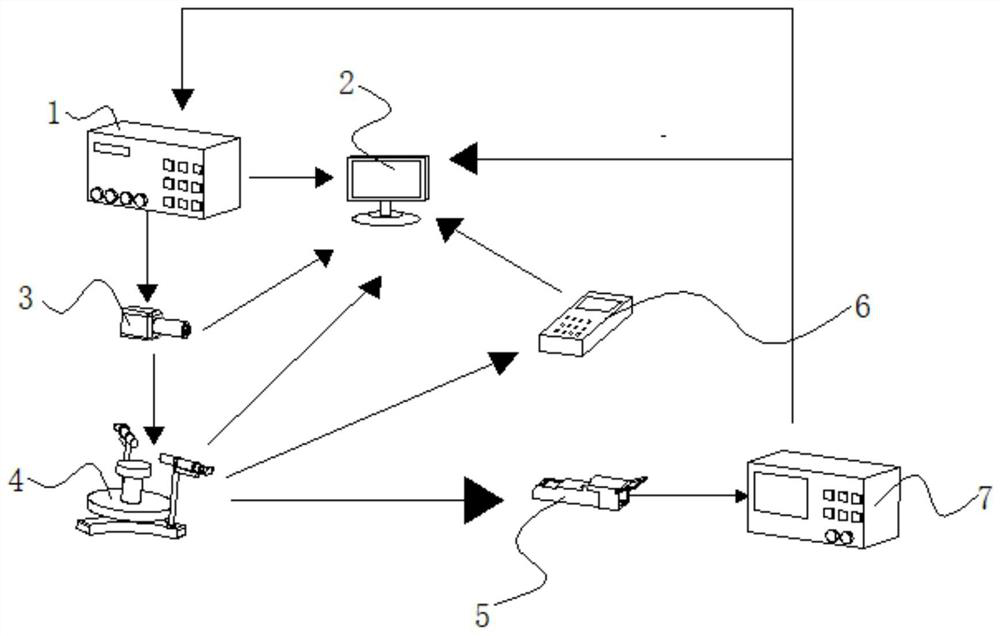
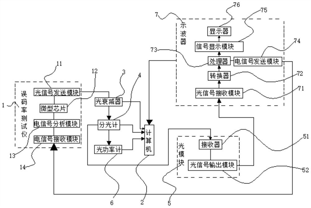
[0019] refer to Figure 1-2 , a kind of optical module receiving end performance testing device, comprises bit error rate tester 1, and bit error rate tester 1 comprises signal transmission module 11, microchip 12, electrical signal analysis module 13 and electrical signal receiving module 14, microchip 12 It is a Flash chip, the signal sending module 11 is electrically connected to the microchip 12, the microchip 12 is electrically connected to the electrical signal analysis module 13, the electrical signal analysis module 13 is electrically connected to the electrical signal receiving module 14, and the bit error rate tester 1 The function of the design is that the...


PUM


Abstract

The invention relates to the technical field of communication testing, in particular to a device for testing the performance of an optical module receiving end, including a bit error rate tester, which includes a signal sending module, a microchip, an electrical signal analysis module, and an electrical signal receiving module. The signal sending module is connected to an optical attenuator through an optical cable, the optical attenuator is electrically connected to a computer, the optical attenuator is connected to a spectrometer through an optical cable, the spectrometer is connected to an optical module and an optical power meter through an optical cable, and a receiver is installed in the optical module and an optical signal output module, the optical signal output module is connected with an oscilloscope through an optical cable, and the oscilloscope includes an optical signal receiving module, a converter, a processor, an electrical signal sending module, a signal display module and a display. The advantage of the present invention is that it can detect the loss and error of the optical signal in the testing process, thereby accurately judging the signal receiving capability of the optical module.

Description

technical field [0001] The invention relates to the technical field of communication testing, in particular to a performance testing device for an optical module receiving end. Background technique [0002] The optical module is composed of optoelectronic devices, functional circuits and optical interfaces. The optoelectronic devices include two parts: transmitting and receiving. Simply put, the function of the optical module is photoelectric conversion. The transmitting end converts electrical signals into optical signals. After transmission through optical fibers, receiving The end converts the optical signal into an electrical signal, and the transmitting part is: input an electrical signal with a certain code rate and process it through an internal driver chip to drive a semiconductor laser (LD) or a light-emitting diode (LED) to emit a modulated optical signal at a corresponding rate. There is an automatic optical power control circuit inside to keep the output optical ...

Claims


Application Information

Patent Timeline
Patent Type & Authority Patents(China)
IPC IPC(8): H04B10/079
CPCH04B10/0795H04B10/07953
Inventor 刘依
Owner 武汉亿德光兴科技有限公司
Why Eureka
Try Eureka