
Method and apparatus of global de-noising for CT imaging

An integral, image technology, applied in the field of integral denoising and devices for CT imaging, which can solve problems such as impracticality

Active Publication Date: 2008-08-06
UNIV OF ROCHESTER
View PDF0 Cites 14 Cited by
  • Summary
  • Abstract
  • Description
  • Claims
  • Application Information

AI Technical Summary

Problems solved by technology

it's not practical

Method used


Image

  • Method and apparatus of global de-noising for CT imaging
  • Method and apparatus of global de-noising for CT imaging
  • Method and apparatus of global de-noising for CT imaging

Examples


Embodiment Construction

[0036] Preferred embodiments of the present invention will be described in detail below with reference to the accompanying drawings, all like numerals designating like elements or steps.

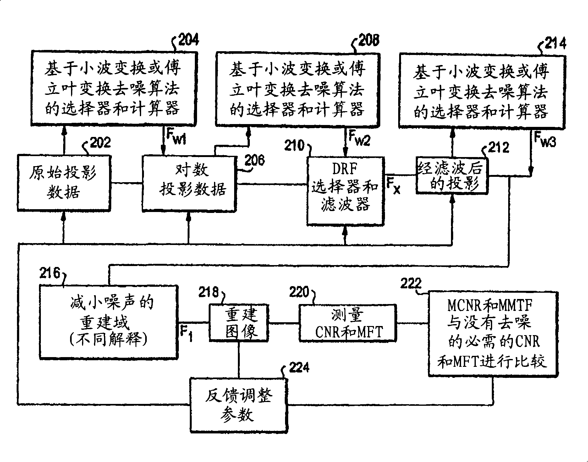
[0037] figure 2 A flowchart of a preferred embodiment is shown. Steps 202 to 214 are performed in the projection domain, while steps 216 to 224 are performed in the reconstruction domain.

[0038] The raw projection data obtained in step 202 is applied in step 204 to the selector and calculator of the WT-based or FT-based denoising algorithm to generate F w1 . Additionally, at step 206 the logarithm of the projection data is calculated. f w1 Logarithmic denoising is applied to the projection data, and the result is applied in step 208 to the selector and calculator of the WT-based or FT-based denoising algorithm to generate F w2 . The logarithm and F of the denoised projection data w2 Applied to the DRF selector and filter 210, which generates the F used to generate the filtered proj...


PUM


Abstract

Raw cone beam tomography projection image data are taken from an object and are denoised by a wavelet domain denoising technique and at least one other denoising technique such as a digital reconstruction filter. The denoised projection image data are then reconstructed into the final tomography image using a cone beam reconstruction algorithm, such as Feldkamp's algorithm.

Description

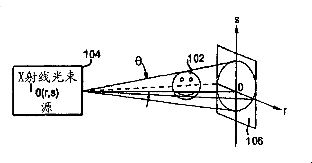
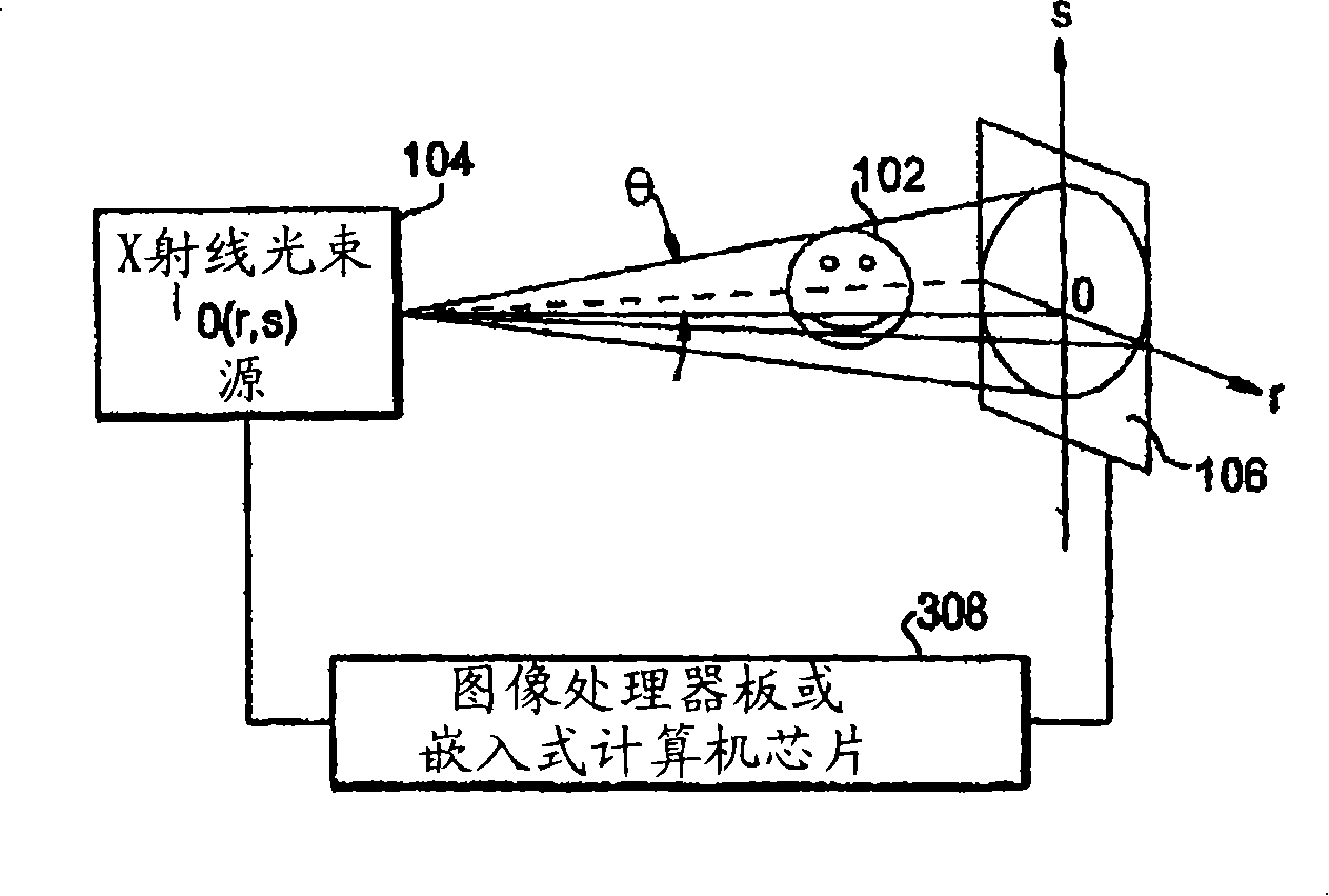
[0001] References to related applications [0002] This application claims the benefit of US Provisional Patent Application No. 60 / 674,335, filed April 25, 2005, the entire disclosure of which is hereby incorporated by reference into this application. [0003] Statement of Government Interest [0004] This invention work was supported in part by the National Institutes of Health. The Government has certain rights in this invention. technical field [0005] The present invention is directed to an efficient overall image denoising algorithm for cone-beam and fan-beam computed tomography (CT) imaging such that the proposed algorithm reduces the noise level while appropriately preserving the spatial resolution of the image , thereby reducing the radiation exposure dose of CT scans while obtaining satisfactory image quality for diagnosis. Background technique [0006] Two types of noise are generally considered in CT images. One is a continuously varying error or round-off er...

Claims


Application Information

Patent Timeline
Patent Type & Authority Applications(China)
IPC IPC(8): A61B6/03
CPCG01N23/046G06T5/002G06T2207/20056G06T2207/20064G06T11/005Y10S378/901G06T5/10G06T2207/10081G01N2223/419G06T5/70
Inventor R·凝
Owner UNIV OF ROCHESTER
Learn More