Rotary hearth furnace and screw rod for discharging reduced iron

A technology for reducing iron and rotary hearth furnaces, applied in furnaces, furnace components, manufacturing converters, etc., and can solve problems such as a lot of time

Inactive Publication Date: 2008-08-13
KOBE STEEL LTD
View PDF0 Cites 2 Cited by
  • Summary
  • Abstract
  • Description
  • Claims
  • Application Information

AI Technical Summary

Problems solved by technology

Also, as for the arrangement of the equipment, a device such as a staplepin is often placed at the upper position of the reduced iron discharge screw, wh

Method used


Image

  • Rotary hearth furnace and screw rod for discharging reduced iron
  • Rotary hearth furnace and screw rod for discharging reduced iron
  • Rotary hearth furnace and screw rod for discharging reduced iron

Examples


Embodiment Construction

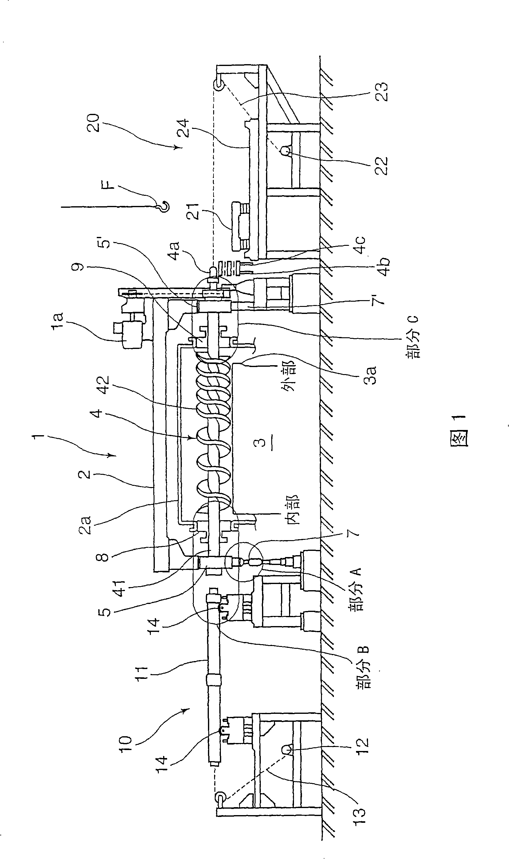
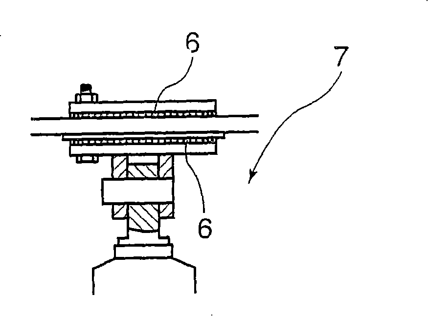
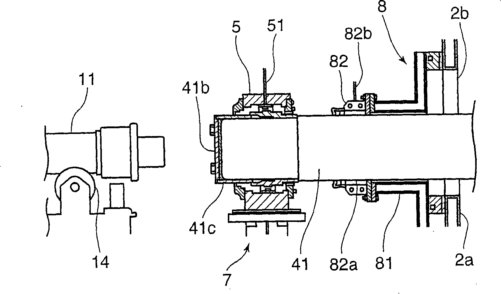
[0024] Hereafter, the rotary hearth furnace and the reduced iron discharge screw of the rotary hearth furnace according to a preferred embodiment of the present invention will be described in conjunction with the accompanying drawings, wherein: Fig. 1 illustrates the cross-sectional composition of the arrangement position of the reduced iron discharge screw of the rotary hearth furnace; figure 2 is a detailed view of part A of FIG. 1; image 3 is a detailed view of part B of FIG. 1; Figure 4 is a detailed view of part C of FIG. 1; Figure 5 is a sectional view of the axis of rotation of the reduced iron discharge screw; Image 6 is a cross-sectional view of the helical blade; and Figure 7 The side configuration of the reduced iron discharge screw is illustrated.

[0025] Reference numeral 1 shown in FIG. 1 denotes a rotary hearth furnace comprising a furnace body 2 having a reduced iron discharge screw 4 constructed as follows for directing the The reduced iron on the ro...


PUM


Abstract

The invention discloses a reduced iron discharging screw of a rotary hearth furnace, which is used for self-forming a hearth reduced iron on the discharging port of periphery, and discharging the hearth reduced iron to the outside of the furnace body. The reduced iron discharging screw has screw blade outside of the rotating axis, the inside of the discharging screw is cooled by the flow of cooling water, and the fireproof layer in the middle is formed outside of the rotating axis.

Description

technical field [0001] The present invention relates to a rotary hearth furnace for producing reduced iron by reducing raw materials consisting of carbon-containing reduced materials and iron oxides, and a screw for discharging reduced iron on a hearth out of the rotary hearth furnace from a discharge port. Background technique [0002] As known to those of ordinary skill, a rotary hearth furnace is used to manufacture reduced iron by reducing a raw material for reducing iron mainly composed of carbon-containing reducing materials and iron oxides. [0003] Such a rotary hearth furnace has a screw that discharges reduced iron on the hearth out of the rotary hearth furnace from a discharge port provided on the outer peripheral side, that is, on the high-speed side where the hearth rotates around a vertical axis. The durability of the reduced iron discharge screw is very important to increase the operating speed of the rotary hearth furnace or the productivity of the reduced ir...

Claims


Application Information

Patent Timeline
IPC IPC(8): C21C5/46F27D3/15
Inventor 占部好浩桥本澄人梅木隆夫
Owner KOBE STEEL LTD
Why Eureka
Try Eureka