Self-forming container

a self-forming, container technology, applied in the field of packaging, can solve the problems of inability to manufacture previous attempts, high cost and complexity of manufacturing, packaging which combine heat shrinkable films with non-shrinkable films, etc., and achieve the effect of less heat shrinkability

Inactive Publication Date: 2016-05-19
BEMIS COMPANY INC
View PDF7 Cites 26 Cited by
  • Summary
  • Abstract
  • Description
  • Claims
  • Application Information

AI Technical Summary

Benefits of technology

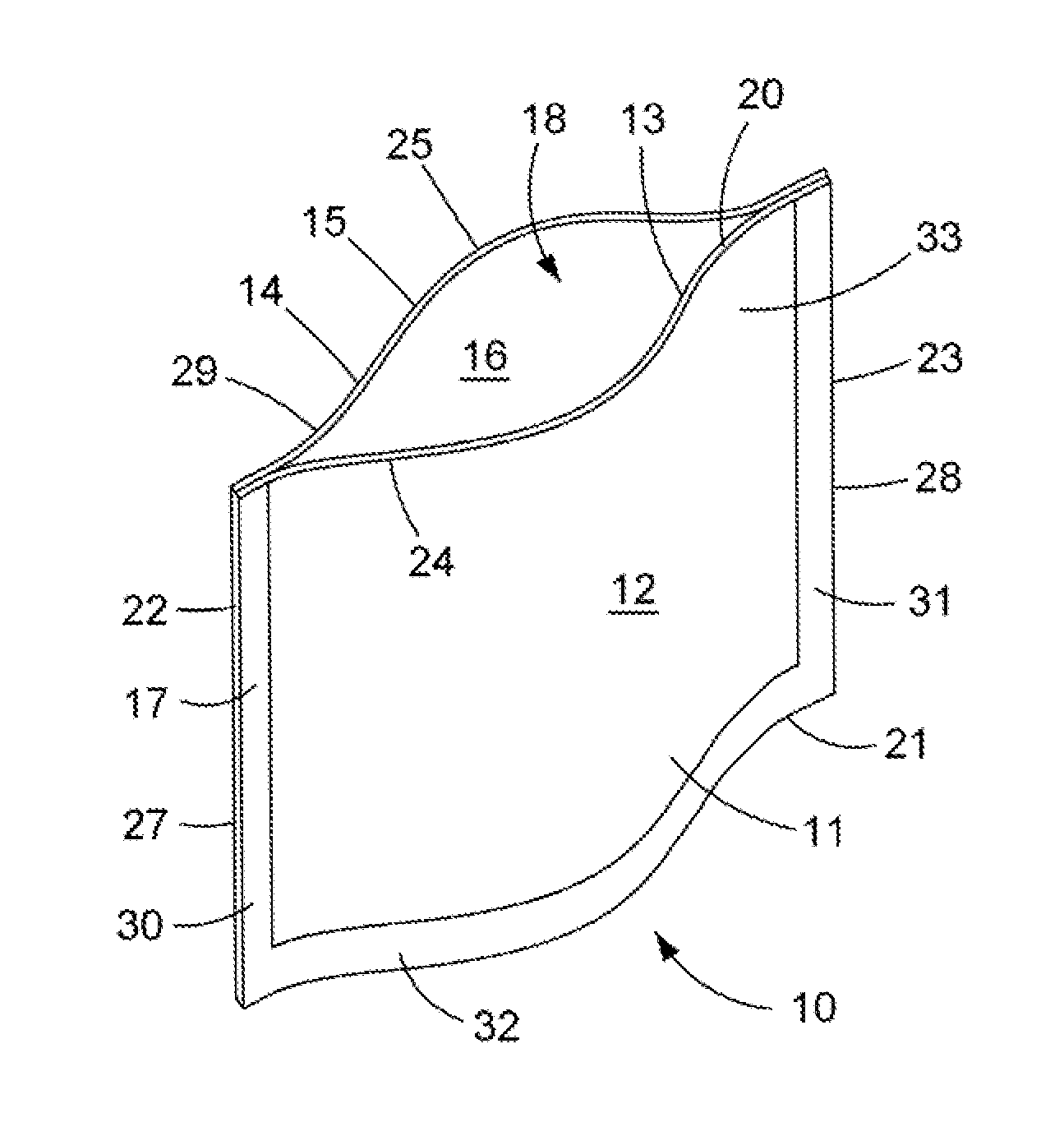
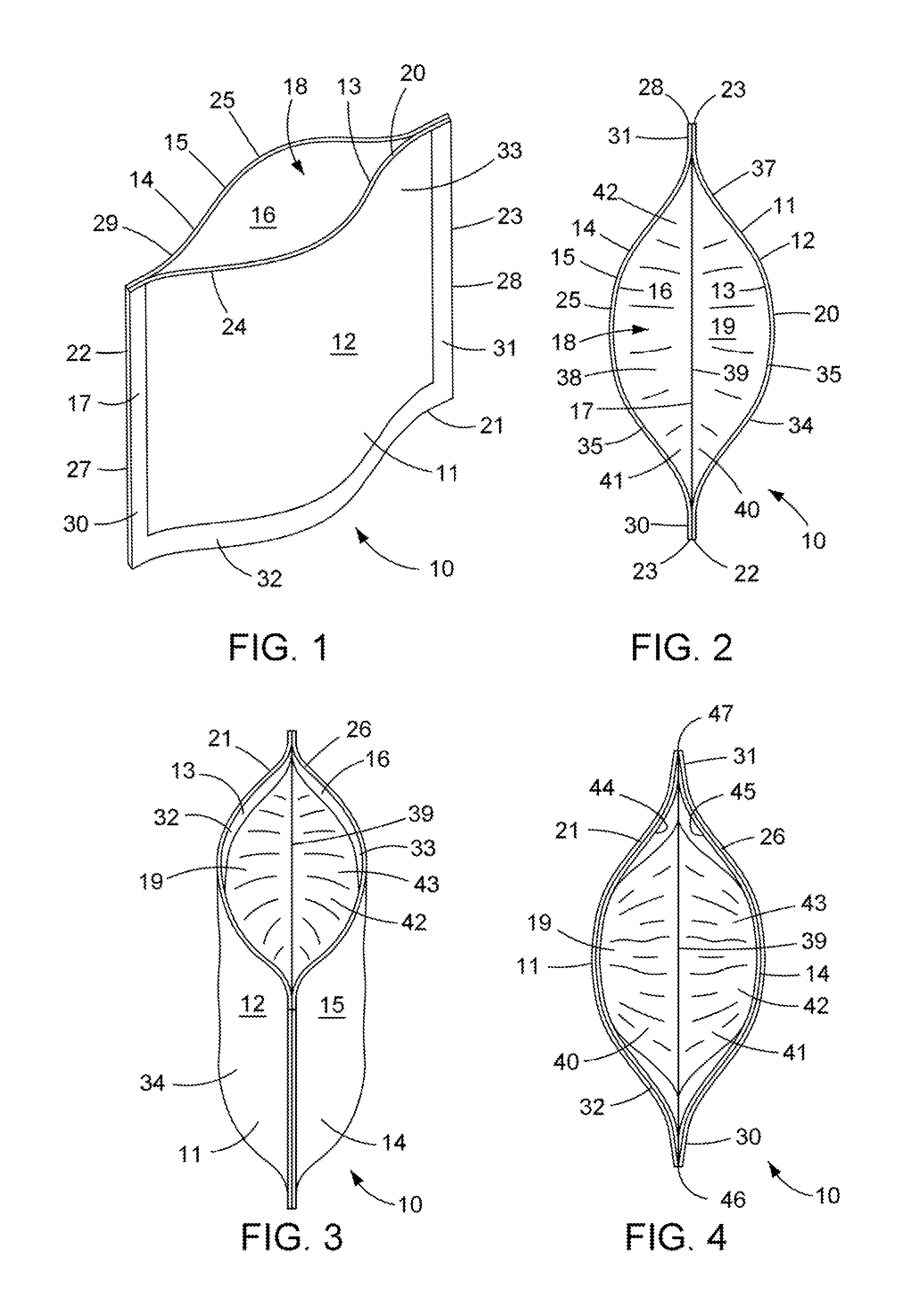
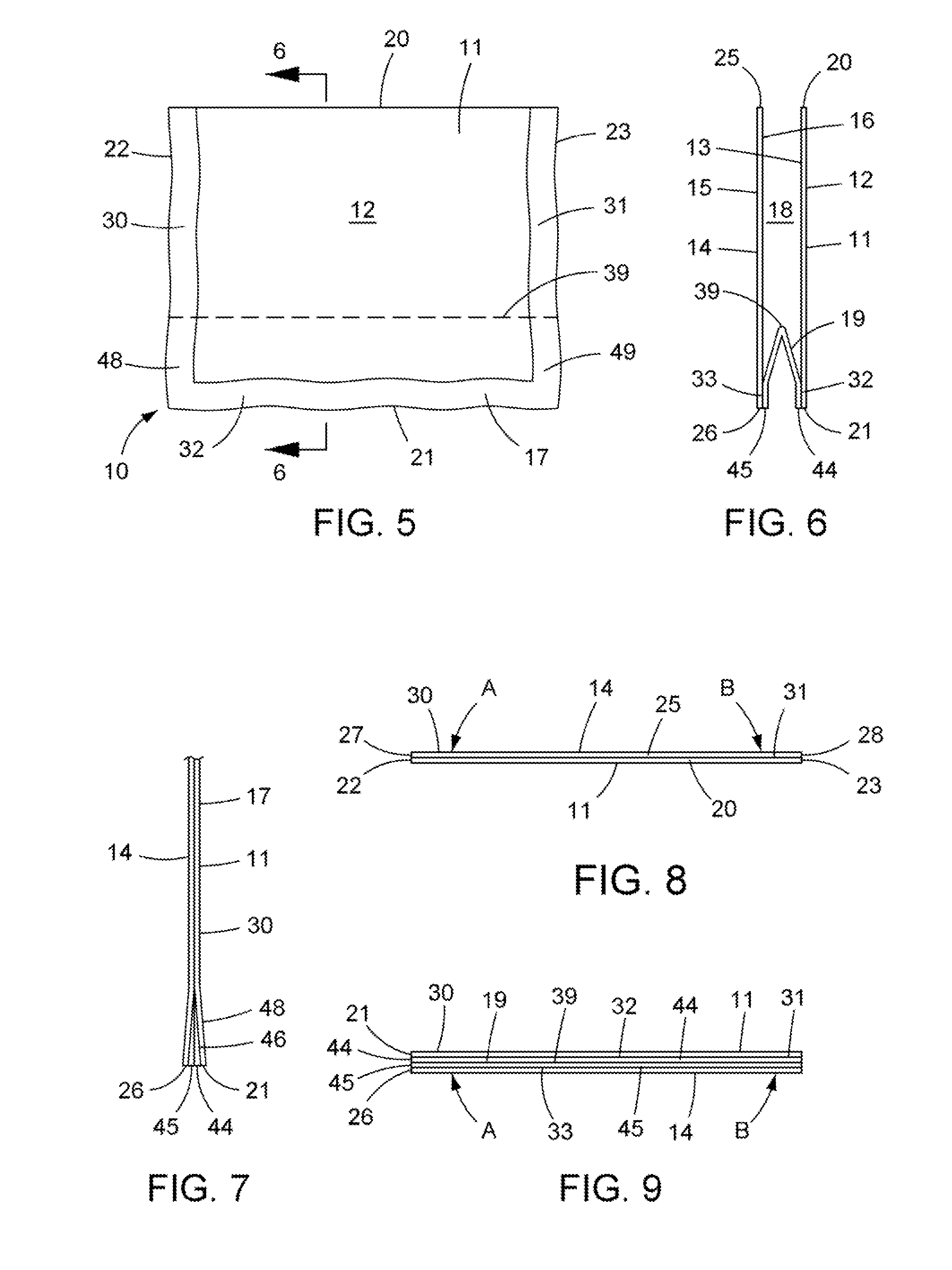
[0011]In one form of the present invention, a self-forming container is provided having (a) a side wall with opposing top and bottom edges connected by an interior side wall surface, and (b) a connecting wall connected to at least first and second opposing portions of the sidewall and forming therewith a container wherein the connecting wall is heat shrinkable in at least one direction and the side wall is less heat shrinkable, and preferably not heat shrinkable, in that same direction. Thus, the container is adapted for heat activated, self-forming into a stand up configuration having a stable base connected to and supporting the side wall.

Problems solved by technology

However, there are few packages which combine heat shrinkable films with non-shrinkable films.
Disadvantageously, the aforementioned packages rely upon their package contents to provide support for a stand up configuration and, absent contents, may easily collapse.
These previous attempts are expensive and complicated to manufacture.

Method used


Image

  • Self-forming container
  • Self-forming container
  • Self-forming container

Examples


example 1

[0127]In Example 1, a uniaxially stretched, heat shrinkable, monolayer film was made and its physical properties tested. A film comprising 70 wt. % of a cyclic olefin copolymer commercially available from Topas Advanced Polymers GmbH under the trade name Topas 8007F-400 was blended with 30 wt. % of a conventional ethylene octene-1 copolymer commercially available from The Dow Chemical Company under the trade name Attane NG 4701G (hereinafter COC:EAO blend). This blend was melt plastified in an extruder and extruded through a slot cast die at a temperature of from 180-250° C. onto a chill roll (temperature ˜55° C.) and subsequently uniaxially oriented in the machine direction by a slot cast MD stretch orientation process similar to that described above at a stretch orientation temperature of ˜85° C. The orientation ratio in the machine direction was 3:1. There was no transverse orientation stretching applied apart from passage of the film through the machine direction rollers. A samp...

example 2

[0130]Another container of the present invention was fabricated, as for Example 1, except with the following changes. The pair of nonshrink side wall panels was replaced with a different multilayer panel material which utilized unoriented PET. These panels were 5 inches high and 7 inches wide and also used a single gusset but having a fold 2¼ inches from the bottom edge. After heat activation, the bottom connecting wall shrank, however the container base was slightly distorted due to the low softening point of the material used in the sidewall relative to the heat activation temperature and coupled with the deep gusset fold and shrink forces attendant to the shrink film utilized.

example 3

[0131]Another container was made, as described for Example 2, except this container used nonshrink side wall panels which were approximately 5 inches high by 6 inches wide and a single gusseted, connecting panel with a 1½ inch fold. The side wall panels and connecting wall utilized the same materials as for Example 2. The container of example 3 was heat activated as for Example 2. There was much less distortion of the base of the example 3 container which result is believed due to use of a shorter fold depth in combination with a shorter panel width. The self-forming container of Example 3 was also equipped with a plastic, double track, reclosable zipper of the type which are commercially available from several manufacturers.


PUM

PropertyMeasurementUnit
shrinkaaaaaaaaaa
shrinkaaaaaaaaaa
shrinkaaaaaaaaaa

Abstract

A self-forming container having a continuous side wall with opposing top and bottom edges connected by an interior side wall surface, said side wall preferably having less than 10% shrink at 90° C., and more preferably being nonshrinkable; and a heat shrinkable connecting wall connected to at least first and second opposing portions of the sidewall and forming therewith a adapted for heat activated self-forming into a stand up con figuration having a stable base connected to and supporting said side wall.

Description

BACKGROUND[0001]1. Technical Field[0002]The present application relates generally to packaging and more specifically to flexible synthetic polymeric packaging.[0003]2. Background Information[0004]Articles such as food, healthcare, personal care, office, home and garden supplies, etc. can be held within a container, e.g. a pouch, for ease of transport and use, and to protect the contents from microbial contamination or contact with air, moisture, dirt, etc. The container is typically sealed to provide a barrier to deleterious materials or energy.[0005]Packaging having multilayer structures where one layer is a heat shrinkable film and another layer is a non-shrinkable film have been disclosed. However, there are few packages which combine heat shrinkable films with non-shrinkable films. One example is U.S. Pat. No. 7,964,255 (Fink et al) assigned to Micro Shaping, Ltd. which discloses packaging using a combination of a first layer of heat shrinkable material and a second layer of non...

Claims


Application Information

Patent Timeline
Patent Type & Authority Applications(United States)
IPC IPC(8): B65D75/00
CPCB65D75/002B65D75/008B65D33/007B65D33/08
Inventor BROSCH, MYCHAL B.MUSSELL, CHRIS S.PRISCAL, MICHAEL D.O'SHEA, RILEY P.
Owner BEMIS COMPANY INC
Why Eureka
Try Eureka