System and method for testing jiggle contact resistance

A technology of contact resistance and contact voltage, applied in the direction of measuring resistance/reactance/impedance, measuring electrical variables, measuring devices, etc., can solve problems such as unfavorable real-time observation and analysis, limited number of channels, inaccurate measurement, etc., and is conducive to real-time observation. Analyze, reduce the fluctuation of fretting amplitude, and improve the effect of experimental efficiency

Inactive Publication Date: 2008-08-06
BEIJING UNIV OF POSTS & TELECOMM
View PDF0 Cites 28 Cited by
  • Summary
  • Abstract
  • Description
  • Claims
  • Application Information

AI Technical Summary

Problems solved by technology

[0017] 1. The micro-motion amplitude of the micro-motion table fluctuates greatly, and the control is not precise
As in the above system, the set micro-motion amplitude is 30 microns, but in actual operation, the micro-motion amplitude of the micro-motion table fluctuates within the range of 30-120 microns, and the control is not accurate
[0018] 2. The micro-motion amplitude of the micro-motion table is not adjustable
The existing fretting contact resistance test system can only perform a single fretting with a certain amplitude, but in practical applications, it is necessary to perform fretting contact resistance testing and analysis on fretting with different amplitudes
[0019] 3. The accuracy of fretting contact resistance test is low
Since the micro-motion frequency, micro-motion amplitude, contact pressure, contact current, temperature and humidity in the actual oper

Method used


Image

  • System and method for testing jiggle contact resistance
  • System and method for testing jiggle contact resistance
  • System and method for testing jiggle contact resistance

Examples


Embodiment Construction

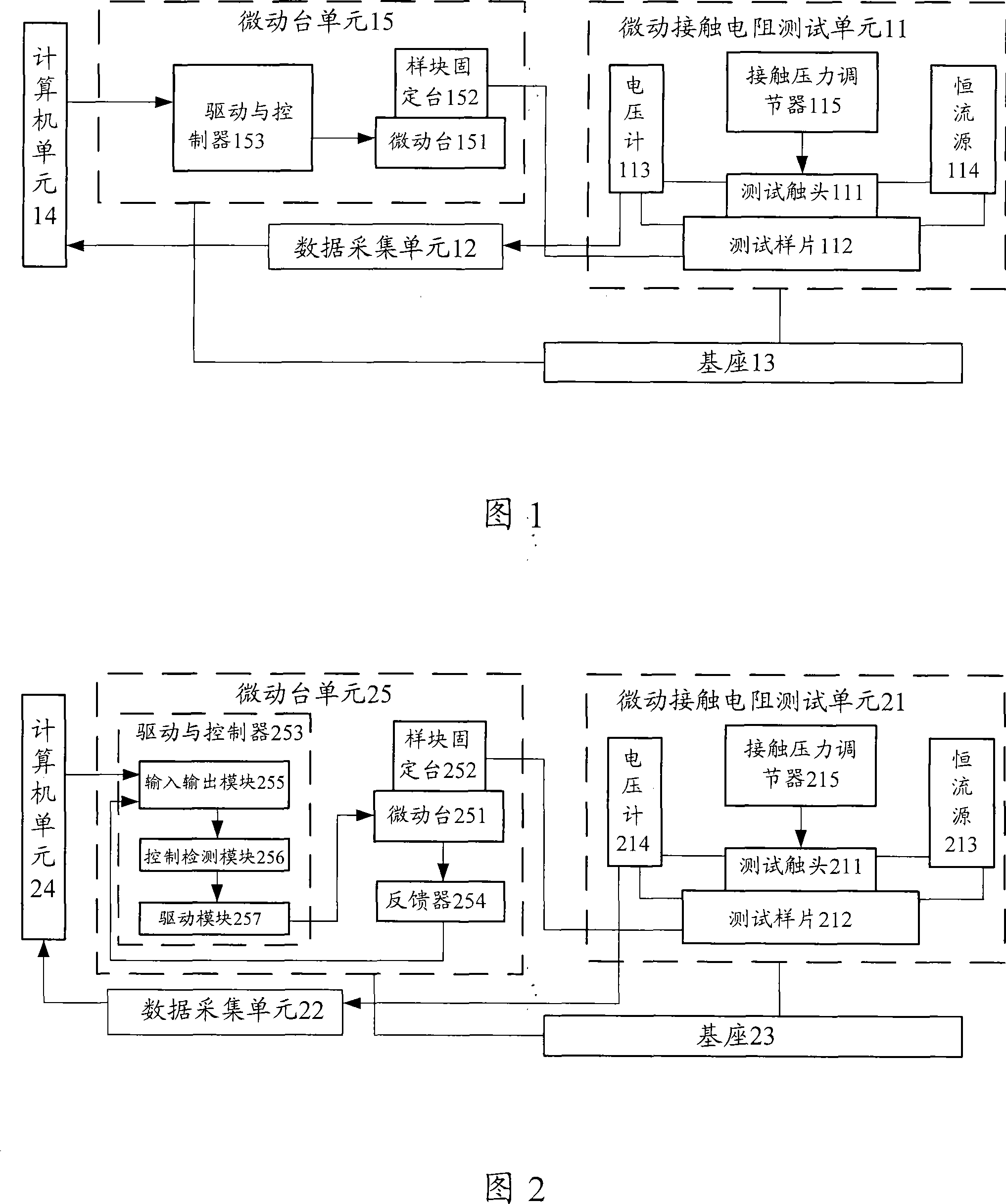
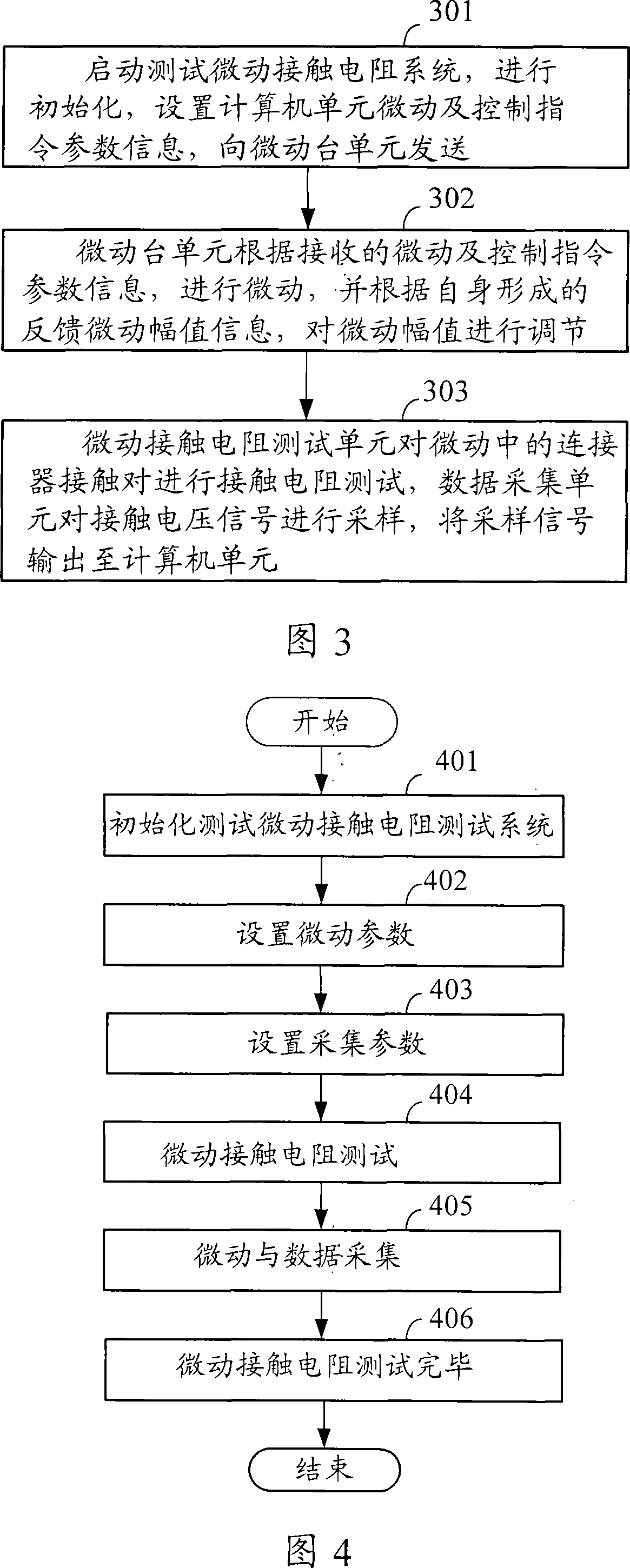
[0069] In the present invention, the micro-motion parameters are set by the computer, and the parameter instructions are sent to the drive and control unit. The drive and control unit controls the micro-motion of the two micro-motion platforms according to the instructions. The sample is fixed on the micro-motion platform, and the contact is vertical to the fixture through the linear bearing Contact with the sample to form a contact pair, the force applying mechanism applies the contact pressure on the contact, the constant current source provides a constant current to the contact pair, the data acquisition card in the voltmeter collects the contact voltage between the sample and the contact, and passes through the PCI bus Transfer to a computer; the computer processes the sampled data and saves it to disk.

[0070] In order to make the purpose, technical solution and advantages of the present invention clearer, the present invention will be further described in detail below in...


PUM


Abstract

The invention discloses a system and a method of testing a micromotion contact resistance. The system comprises a microchecker unit, a micromotion contact resistance test unit, a data acquisition unit and a computer unit. The method has the following steps that a test micromotion contact resistance system is started for initialization, and the micromotion and control command parameter information is set in the computer unit and sent to the microchecker unit; the microchecker unit carries out micromotion according to the received micromotion and control command parameter information and adjusts the micromotion amplitude according to the self-formed micromotion feedback information; the micromotion contact resistance test unit carries out contact resistance test for a connector contact pair in micromotion, and the data acquisition unit samples the contact voltage signal and outputs the sampled signal to the computer unit for data storage, processing and graphic display. The system and the method of measuring a micromotion contact resistance are capable of regulating and controlling test parameters according to requirements, widening the test channel of the micromotion contact resistance and improving the accuracy of micromotion contact resistance test.

Description

technical field [0001] The invention relates to a contact resistance testing technology of a low-voltage electrical appliance connector, in particular to a system and method for testing fretting contact resistance. Background technique [0002] In the communication system or power transmission system, there are a large number of electrical connection links. Due to the influence of external environmental factors, such as impact, collision, vibration, cold and heat cycle, etc., the electrical contact contacts of the connector may change relatively slightly. (fretting), the surface of the connector is worn, and the debris generated by the wear is exposed to the atmosphere, oxidized to form an insulating oxide film layer, and remains on the electrical contact surface, thereby affecting the electrical contact performance of the connector and causing the contact of the connector The resistance value increases or even breaks the circuit. The phenomenon of contact failure caused by ...

Claims


Application Information

Patent Timeline
IPC IPC(8): G01R27/02
Inventor 许良军芦娜白惠贤罗东于海涛
Owner BEIJING UNIV OF POSTS & TELECOMM
Why Eureka
Try Eureka