Door lock jointing construction

A technology for connecting structures and door locks. It is used in building locks, building structures, and non-mechanical drive-operated locks. It can solve problems such as limited surface area, safety concerns, and impact on product markets.

Inactive Publication Date: 2008-08-13
上海欧意机电五金有限公司
View PDF0 Cites 19 Cited by
  • Summary
  • Abstract
  • Description
  • Claims
  • Application Information

AI Technical Summary

Problems solved by technology

In order to improve the magnetic force, under the condition of constant and fixed material saturation magnetic flux density, the surface area can only be increased generally. However, the surface area of ​​the door is often limited, and the increase of the surface ar

Method used


Image

  • Door lock jointing construction
  • Door lock jointing construction
  • Door lock jointing construction

Examples


Embodiment

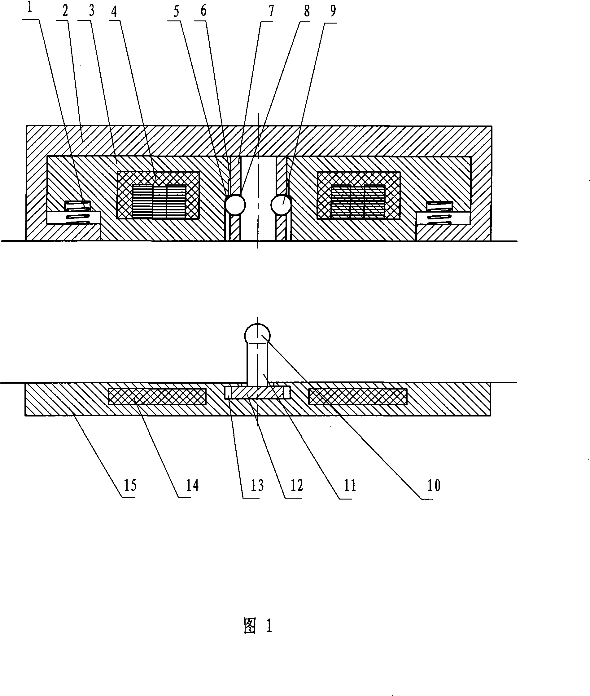
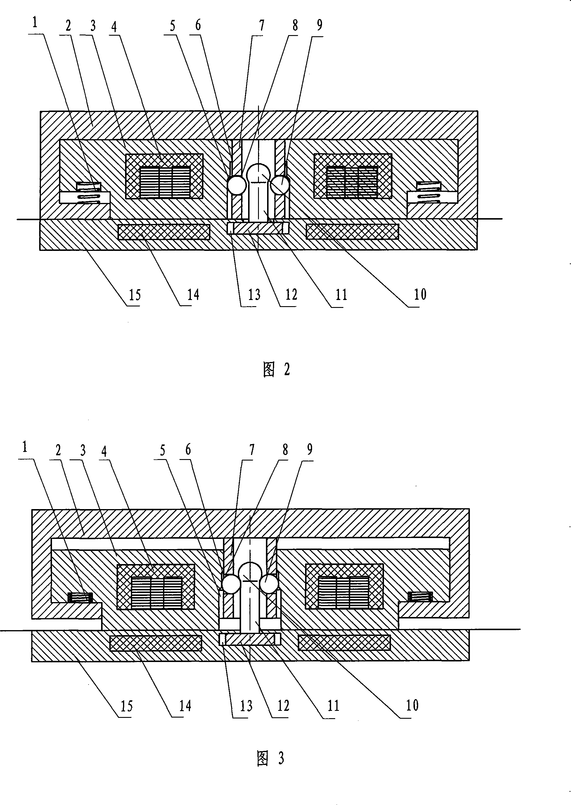
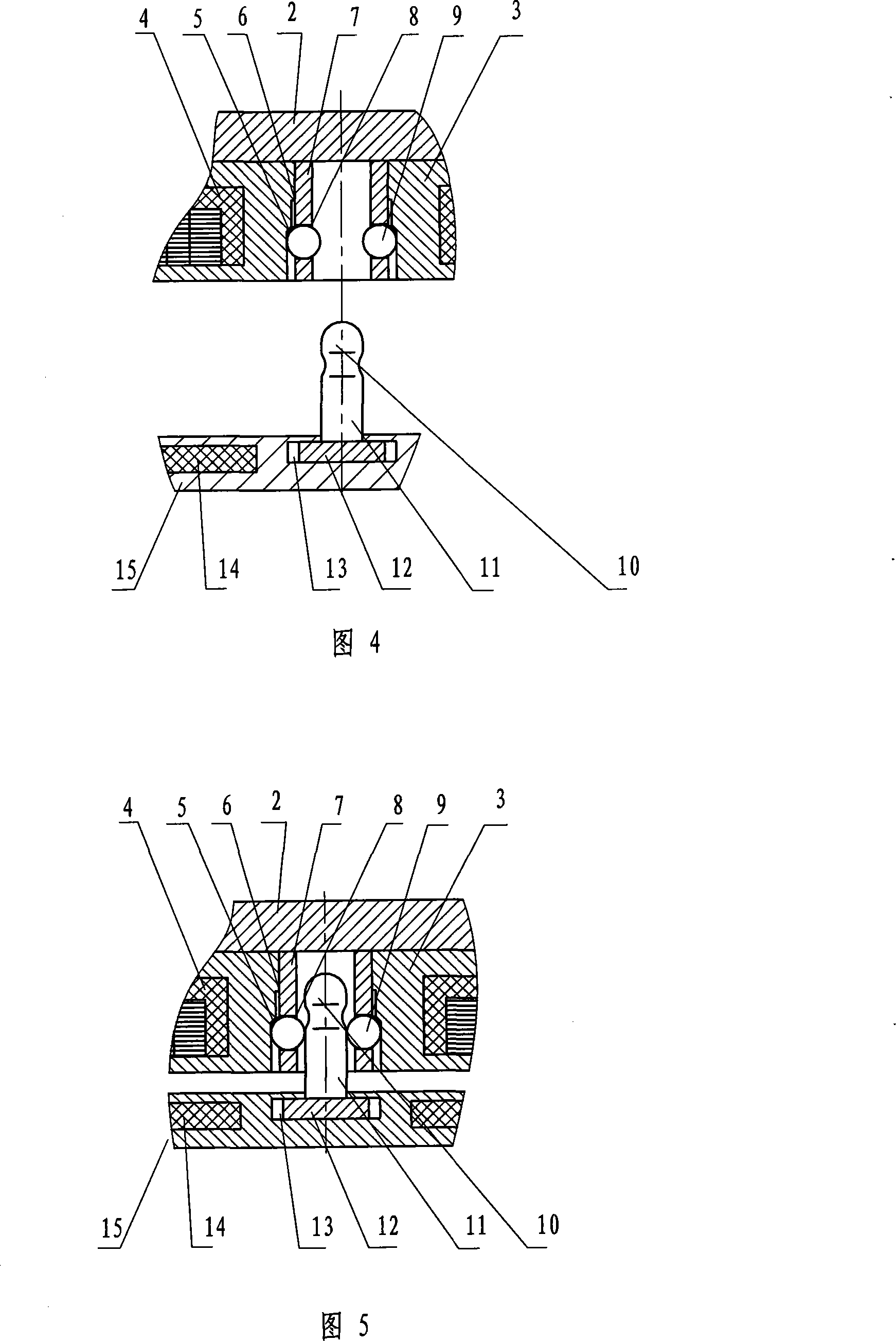
[0037]A connection structure of a door lock, two door panels facing each other, a protruding ball stick is set on the base plate 15 of one door panel, and a movable ball locking mechanism is set on the base 2 of the other door panel, and the protruding ball stick is, One end of the protrusion perpendicular to the door panel is a cylindrical rod with a ball 10, and the diameter of the ball 10 is greater than the diameter of the cylinder 11. The movable ball blocking mechanism is as follows: on the base 2, a ball-holding chamber 5 with a cavity in the middle is vertically arranged, and the inner diameter of the ball-holding chamber 5 is larger than the diameter of the ball 10 of the protruding ball stick; at the mouth of the ball-holding chamber 5 , set the limit ball control mechanism that can change the size of the caliber. When the protruding bat on a door panel is inserted into the ball-holding chamber 5 of the movable ball-blocking mechanism on the other door-plate, and the...


PUM


Abstract

The invention is a counterblow door lock structure which is opposite direction motion between door and doorframe. Door lock connecting structure, the one end of the convex area which is perpendicular to the cardinal plate of the door board is the cylinder stick, the stick whose spherical equivalent diameter is bigger than cylinder diametric is a knuckling stick, and other door board is installed movable block ball mechanism. A ball cavity whose middle is hollow space is perpendicular to the base of the flat-plate, the interior diameter of the ball cavity is bigger than that of the knuckling stick, a limit ball control mechanism whose caliber size is changeable is installed at the mouth of the ball cavity. The limit ball control mechanism is: at least two round holes are radial at the wall part of the ball cavity, ball bearing is placed in the round hole, a slipper block which can move along the axial cord of the ball cavity around the ball cavity and the inner wall has vary in size step hole is configured at the base of the ball cavity, the technical project achieves that the little electromagnetic force transforms to the large door leaves engaging force; after the door leaves closed, the door leaves is permitting opened through the method of the electromagnetic control etc; and its operations is smooth, steady and convenience.

Description

(1) Technical field [0001] The invention relates to a door lock component, in particular to a door and a door frame, or two sliding doors, or one is fixed and the other is moving, and the two move toward each other so that they can be locked by confrontation, and cannot be locked without authorization. A connection structure that enables separation. (2) Background technology [0002] As we all know, in door locks, especially a mechanism for connecting the door and the door frame, or two sliding doors, or one is fixed and the other is moved, and the two move towards each other so that they are locked by confrontation, magnetic doors are generally used. Lock. The main structure of the magnetic door lock is that the electromagnet is fixed on one side of the door or the door frame, and the relay iron plate is fixed on the door plate corresponding to the position of the electromagnet. This type of door lock has a special advantage, that is, when the door is closed, the two are ...

Claims


Application Information

Patent Timeline
IPC IPC(8): E05B47/00E05B65/08
Inventor 张宗志
Owner 上海欧意机电五金有限公司
Why Eureka
Try Eureka