Separator for direct methanol fuel cell

A methanol fuel cell and separator technology, applied in the separator field

Inactive Publication Date: 2008-08-13
SAMSUNG SDI CO LTD
View PDF2 Cites 2 Cited by
  • Summary
  • Abstract
  • Description
  • Claims
  • Application Information

AI Technical Summary

Problems solved by technology

However, this well-suited situation for mo

Method used


Image

  • Separator for direct methanol fuel cell
  • Separator for direct methanol fuel cell
  • Separator for direct methanol fuel cell

Examples


Embodiment Construction

[0038] The present invention will now be described more fully with reference to the accompanying drawings, in which exemplary embodiments of the invention are shown.

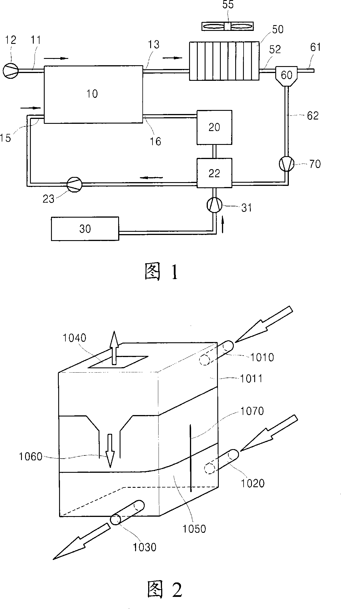
[0039] FIG. 1 illustrates the structure of a direct methanol fuel cell (DMFC). Electrochemical processes (which are not the object of the present invention and therefore need not be described in more detail) take place in the fuel cell stack 10 . The reaction product on the anode side contains CO 2 Liquid / gas mixture with water.

[0040] Air is supplied to the fuel cell stack 10 by means of a pump 12 through an inlet 11 on the cathode side. The supplied air can be discharged from the cathode side outlet 13 of the fuel cell stack 10 and cooled by the fan 55 and the heat exchanger 50 . Cooled air and condensed liquid thus exit heat exchanger 50 through outlet 52 to be provided to air separator 60 . The air separator 60 is connected via a corresponding line to the outlet valve 61 and to the mixer 22 via a line ...


PUM

PropertyMeasurementUnit
Thicknessaaaaaaaaaa

Abstract

A separator is provided for separating a gas/liquid mixture in a direct methanol fuel cell (DMFC). The separator has a closed channel, the closed channel has at least one channel part, the wall of the channel part is completely or partly formed by a hydrophobic, gas-permeable membrane, wherein the cross-sectional area of ​​the channel decreases continuously or stepwise from the inlet to the outlet, and , the wall part of the channel which is not formed by the membrane is predetermined by the one-piece machining body.

Description

[0001] Cross references to related patent applications [0002] This application claims the benefit of European Patent Application No. 07101794.1 filed on February 6, 2007 and Korean Patent Application No. 10-2008-0009021 filed on January 29, 2008, the entire disclosures of which are incorporated by reference was incorporated into this article. technical field [0003] The present invention relates to a separator for a direct methanol fuel cell, and more particularly, to a separator for separating a gas / liquid mixture of a direct methanol fuel cell. Background technique [0004] A fuel cell is a primary battery that converts the chemical reaction energy of a continuously supplied fuel and an oxidant into electrical energy. Typically, a fuel cell includes two electrodes separated by a membrane or by a dielectric. The anode is surrounded by a flow of fuel, such as hydrogen, methane or methanol, and the fuel is oxidized therein. The cathode is surrounded by a flow of an oxid...

Claims


Application Information

Patent Timeline
IPC IPC(8): H01M8/02
CPCB01D53/22B01D63/081B01D63/087B01D69/06B01D71/36B01D2257/504B01D2313/08H01M8/0265H01M8/04164H01M8/04186H01M8/0668H01M8/1011Y02E60/50Y02C20/40H01M8/02H01M8/10
Inventor 斯蒂芬·莫格尔迭戈·莱拉因马蒂亚斯·布洛诺德
Owner SAMSUNG SDI CO LTD
Why Eureka
Try Eureka