Nano-photocatalysis air purge clarification system

An air cleaning and purification system technology, applied in irradiation, deodorization, disinfection, etc., to ensure recycling and avoid secondary pollution

Inactive Publication Date: 2008-08-20
SHAANXI NORMAL UNIV
View PDF1 Cites 7 Cited by
  • Summary
  • Abstract
  • Description
  • Claims
  • Application Information

AI Technical Summary

Problems solved by technology

[0003] The technical problem to be solved by the present invention is to overcome the shortcomings of the above-mentioned combined air purification and sterilization device, and provide a device with reasonable design, simple structure, convenient use and maintenance, strong ability to capture pollutants, fast purification speed, high efficiency, and no secondary pollution. Nano photocatalytic air cleaning and purification system

Method used


Image

  • Nano-photocatalysis air purge clarification system

Examples


Embodiment 1

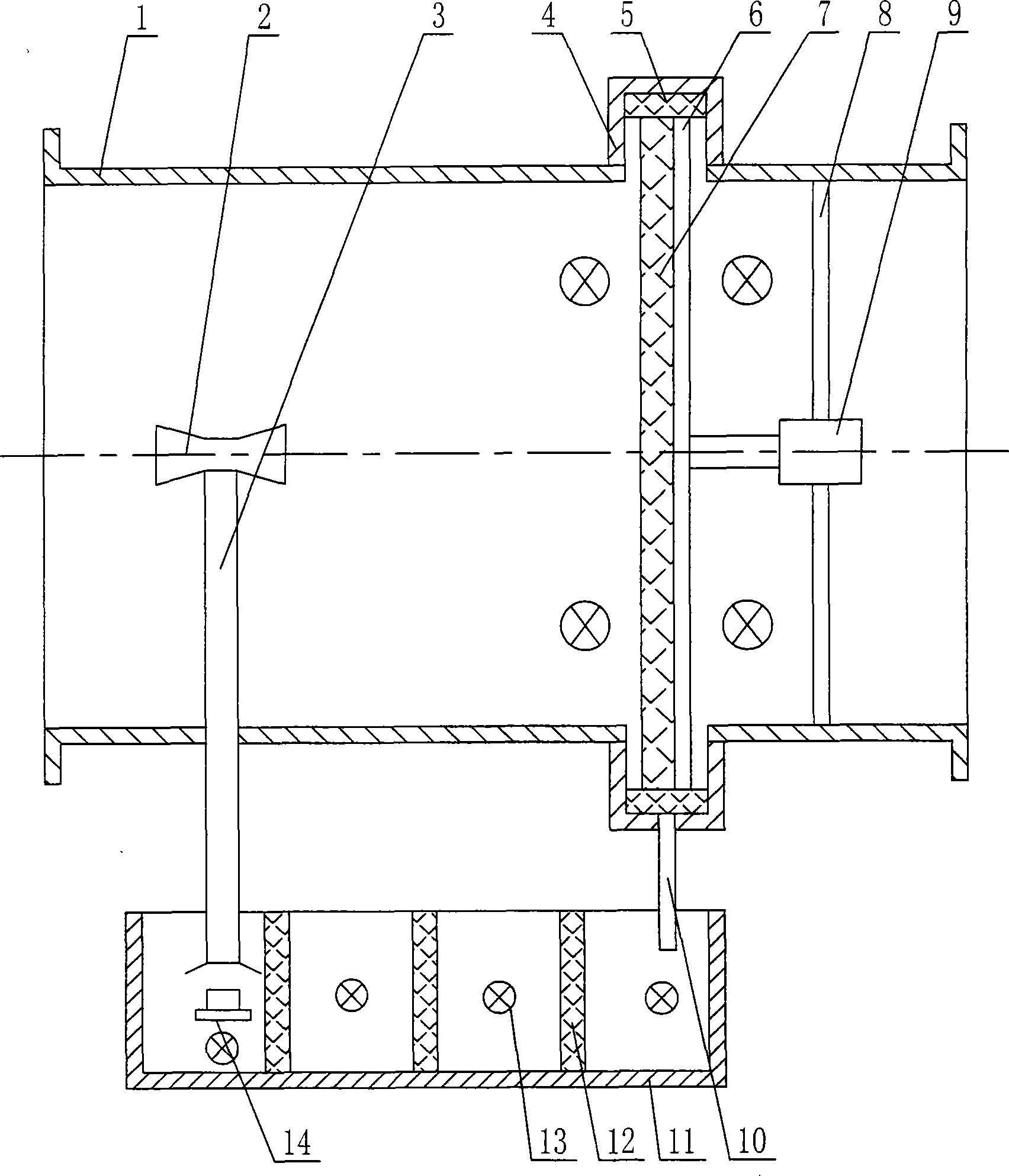
[0015] exist figure 1 Among them, the nanophotocatalytic air cleaning and purification system of this embodiment consists of a housing 1, a water mist nozzle 2, a mist guide 3, a collecting tank 4, a water absorption belt 5, a turntable skeleton 6, a demisting photocatalytic three-dimensional net 7, The motor bracket 8, the motor 9, the water outlet pipe 10, the return water storage and purification tank 11, the photocatalytic plate 12, the ultraviolet lamp 13, and the self-floating ultrasonic atomizer 14 are connected to form.

[0016] The downstream side of the airflow direction in the housing 1 is connected with the housing 1 to form a collecting tank 4 , the collecting tank 4 communicates with the housing 1 , and a water-absorbing belt 5 is installed in the collecting tank 4 . A return water storage purification tank 11 is placed below the outer surface of the housing 1, and the bottom of the collecting tank 4 is threadedly connected with an outlet pipe 10, and the lower e...

Embodiment 2

[0018] In this embodiment, the dehazing photocatalytic three-dimensional net 7 is loaded with nano-TiO 2 The photocatalyst is made of foamed stainless steel, and the demisting photocatalytic three-dimensional net 7 is disc-shaped with a thickness of 8mm. Other components and the coupling relationship of the components are the same as in Embodiment 1.

Embodiment 3

[0020] In this embodiment, the dehazing photocatalytic three-dimensional net 7 is loaded with nano-TiO 2 The photocatalyst is made of foamed stainless steel, and the demisting photocatalytic three-dimensional net 7 is disc-shaped with a thickness of 20mm. Other components and the coupling relationship of the components are the same as in Embodiment 1.


PUM


Abstract

The invention relates to a nanometer photocatalyzing air rinsing and purifying system, comprising a storing and purifying groove for return water arranged below the external surface of a casing body with two openings at both ends, wherein a sprayer is positioned in the storing and purifying groove for return water; a fog directing pipe is arranged on the upper reach of the airflow in the casing body above a sprayer in the storing and purifying groove for return water, penetrating the lower sidewall of the casing body; a water-fog spray pipe is arranged on the upper end of a fog-directing pipe; a defogging photocatalyzing three-dimensional net and a ultraviolet lamp are arranged on the lower reach of the airflow in the casing body; a flow-congregating groove is arranged on the casing body communicated with the inner part of the casing body; a water outlet pipe is arranged on the bottom part of the flow-congregating groove, communicating with the inner part of the storing and purifying groove for return water; a water absorbing belt is arranged in the flow-congregating groove; a motor support for a motor is arranged inside the casing body; the defogging photocatalyzing three-dimensional net is positioned on a rotary table frame connected with an output shaft of the motor; a photocatalyzing plugboard and the ultraviolet lamp are positioned in the storing and purifying groove for return water. The nanometer photocatalyzing air rinsing and purifying system has the advantages of simple structure, high purifying efficiency, small air lock, high water-air separation efficiency, and can be used for sterilization and purification of ventilating pipelines of central air conditioners.

Description

technical field [0001] The invention belongs to the field of air purification, and in particular relates to a nano photocatalysis air cleaning and purification system which combines nano photocatalysis technology with water body atomization and dust suction technology. Background technique [0002] The threat of air pollution to human survival is well known, and indoor air pollution is closely related to people's lives. Therefore, the research on indoor air purification technology has been a research hotspot in related fields in recent years, especially for public places with a large flow of people. The research on advanced air purification methods and devices has aroused the great interest of professional and technical personnel. Air purification methods can be broadly divided into two categories, namely dry purification and wet purification. Dry purification includes traditional mechanical filtration purification, electrostatic filtration purification and emerging nano ph...

Claims


Application Information

Patent Timeline
Patent Type & Authority Applications(China)
IPC IPC(8): A61L9/22A61L9/20
Inventor 张宗权杨宗立鲁百佐刘志存
Owner SHAANXI NORMAL UNIV
Why Eureka
Try Eureka