Magnetic thermal field cooperate with oxygen-enriched air generating device

An oxygen-enriched air generating device technology, applied in the direction of oxygen preparation, etc., to achieve the effect of simple device structure, low energy consumption and wide application range

Inactive Publication Date: 2008-08-20
SHAANXI NORMAL UNIV
View PDF3 Cites 6 Cited by
  • Summary
  • Abstract
  • Description
  • Claims
  • Application Information

AI Technical Summary

Problems solved by technology

[0003] The technical problem to be solved by the present invention is to overcome the shortcomings of the above-mentioned oxygen-enriched air generating device, and provide a device with reasonable design, simple structure, co

Method used


Image

  • Magnetic thermal field cooperate with oxygen-enriched air generating device
  • Magnetic thermal field cooperate with oxygen-enriched air generating device
  • Magnetic thermal field cooperate with oxygen-enriched air generating device

Examples


Embodiment 1

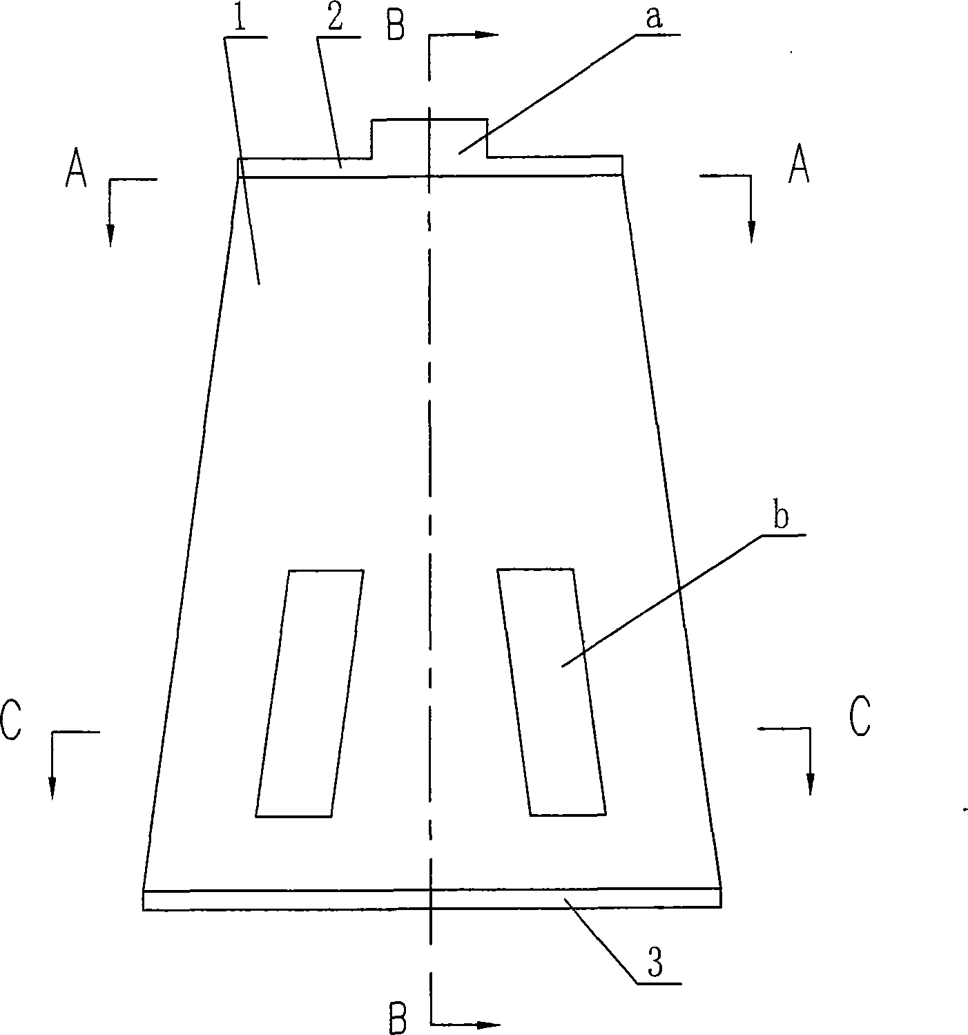
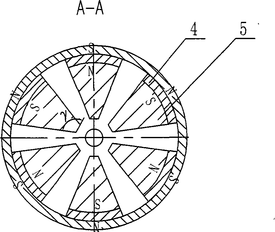
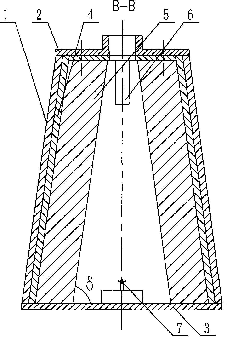
[0027] exist Figure 1~4 Among them, the magnetothermal field cooperative oxygen-enriched air generating device of this embodiment is composed of a housing 1, an upper cover 2, a base 3, a permanent magnet 4, a magnetic shoe 5, a heater 6, and an air negative ion generator 7.

[0028] The shape of the housing 1 of this embodiment is a circular truncated tubular housing, which is a housing made of magnetically conductive material. The upper end of the housing 1 is fixedly connected with a loam cake 2. The loam cake 2 is a loam cake made of non-magnetic material. The center position is processed with an air outlet a, the lower end of the housing 1 is fixedly connected with a base 3, the base 3 is a non-magnetic material base 3, the inner wall of the housing 1 is evenly distributed in the circumferential direction with 6 permanent magnets 4, and the permanent magnet 4 at the lower part of the side wall There are 6 air inlets b processed between them, and the shape of the air inle...

Embodiment 2

[0030] The shape of the casing 1 of this embodiment is a truncated conical tubular casing. The inner wall of the casing 1 is evenly distributed with 6 permanent magnets 4 in the circumferential direction, and 6 air inlets b are processed between the permanent magnets 4 at the lower part of the side wall. The shape is the same as in Example 1. The shape of the permanent magnet 4 cross-section is a tile-shaped body structure, and the length ratio of the outer circular arc line of the upper and lower end faces of the tile-shaped permanent magnet 4 is 1. The inner surface of the permanent magnet 4 is adsorbed with a magnetic shoe 5, and the radial side of the permanent magnet 4 and the magnet. The radial side of the shoe 5 is in the same plane, the angle γ between the radial side of the upper end of the magnetic shoe 5 and the inner end surface is 110°, the angle δ between the inner surface of the magnetic shoe 5 and the base 3 is 45°, adjacent There is a gap communicating with th...

Embodiment 3

[0032]The shape of the housing 1 of this embodiment is a truncated conical tubular housing, and the shape of the housing 1 is a truncated circular tubular housing. The inner wall of the housing 1 is evenly distributed circumferentially with 6 permanent magnets 4, and between the permanent magnets 4 at the bottom of the side wall There are 6 air inlets b processed, and the shape of the air inlets b is the same as that of embodiment 1. The shape of the permanent magnet 4 cross-section is a tile-shaped body structure, and the length ratio of the outer circular arc line of the upper and lower end faces of the tile-shaped permanent magnet 4 is 1. The inner surface of the permanent magnet 4 is adsorbed with a magnetic shoe 5, and the radial side of the permanent magnet 4 and the magnet. The radial sides of the shoe 5 are in the same plane, the angle γ between the radial side of the upper end of the magnetic shoe 5 and the inner end surface is 110°, the angle δ between the inner surfa...


PUM

PropertyMeasurementUnit
Magnetic inductionaaaaaaaaaa

Abstract

The invention relates to a magneto-thermal field synergistic oxygen-enriched air generating device; a casing is a stage tubular body or a column tubular body, an upper cover with an air outlet a is arranged on upper end of the casing, a base is arranged at lower end of the casing, permanent magnets with magnetic shoes are circumferentially and evenly arranged in the casing, polarities of adjacent and opposite permanent magnets are different, an air inlet b is arrange between lower part of lateral side of the casing and the permanent magnets, clearance which is communicated with the air inlet b is retained between adjacent permanent magnets and magnetic shoes, forming a convergence type air inlet channel which is communicated with the air inlet b from the external to the internal; lateral side of radial direction of the permanent magnets is at the same plane with the laterals side of radial direction of the magnetic shoes, a convergence type air outlet channel is formed from the upper part to the lower part among the circumferentially adjacent permanent magnets, adjacent and opposite magnetic shoes in the casing, a heater is arranged at the air outlet a of the upper cover in the casing and an air negative ion generating device is arranged on the base in the casing. The oxygen-enriched air generating device has the advantages that the device can be used for indoor oxygen-enriching and ventilating and can also be used as the oxygen-enriched source of combustion as well as oxygen-charging source of water body.

Description

technical field [0001] The invention belongs to the technical field of air separation, and in particular relates to a device for generating oxygen-enriched air by utilizing the combined action of a gradient magnetic field and a gradient temperature field. Background technique [0002] The wide application of oxygen-enriched air in oxygen-enriched ventilation in living environment, oxygen-enriched combustion in energy saving and emission reduction, and enriched oxidation treatment of water body has attracted widespread attention in the field of environmental engineering. At present, there are many ways to separate oxygen from air to form oxygen-enriched air, but using the magnetic oxygen accumulation effect to separate oxygen from air to prepare oxygen-enriched air is considered to be a method of energy saving, environmental protection and high efficiency, and has been favored by professionals. extensive attention. At present, there are many patent applications. The patent ...

Claims


Application Information

Patent Timeline
IPC IPC(8): C01B13/02
Inventor 张宗权吴俊林袁胜利鲁百佐杨宗立
Owner SHAANXI NORMAL UNIV
Why Eureka
Try Eureka