
Direct twisting type twisting technique

A direct-twisting and technological technology, applied in the field of direct-combined twisting process, can solve problems such as staying in theoretical exploration, and achieve the effects of outstanding economic benefits, reduced energy consumption, and low energy consumption

Active Publication Date: 2011-05-11
北京市文化科技融资租赁股份有限公司
View PDF5 Cites 0 Cited by
  • Summary
  • Abstract
  • Description
  • Claims
  • Application Information

AI Technical Summary

Problems solved by technology

[0009] However, at present, the direct twisting process has not been industrialized in China, and only stays in the stage of theoretical exploration, and the direct twisting process suitable for industrial applications for fine denier yarns such as embroidery thread, nylon, polyester, rayon, and sewing thread has not yet been developed. see the report

Method used

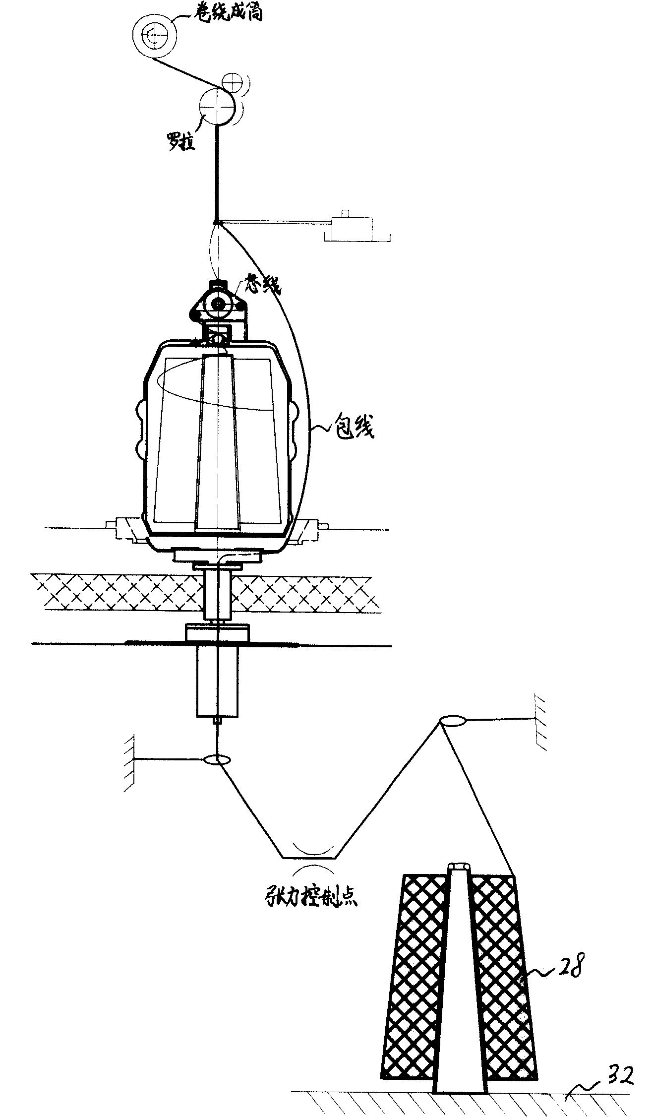
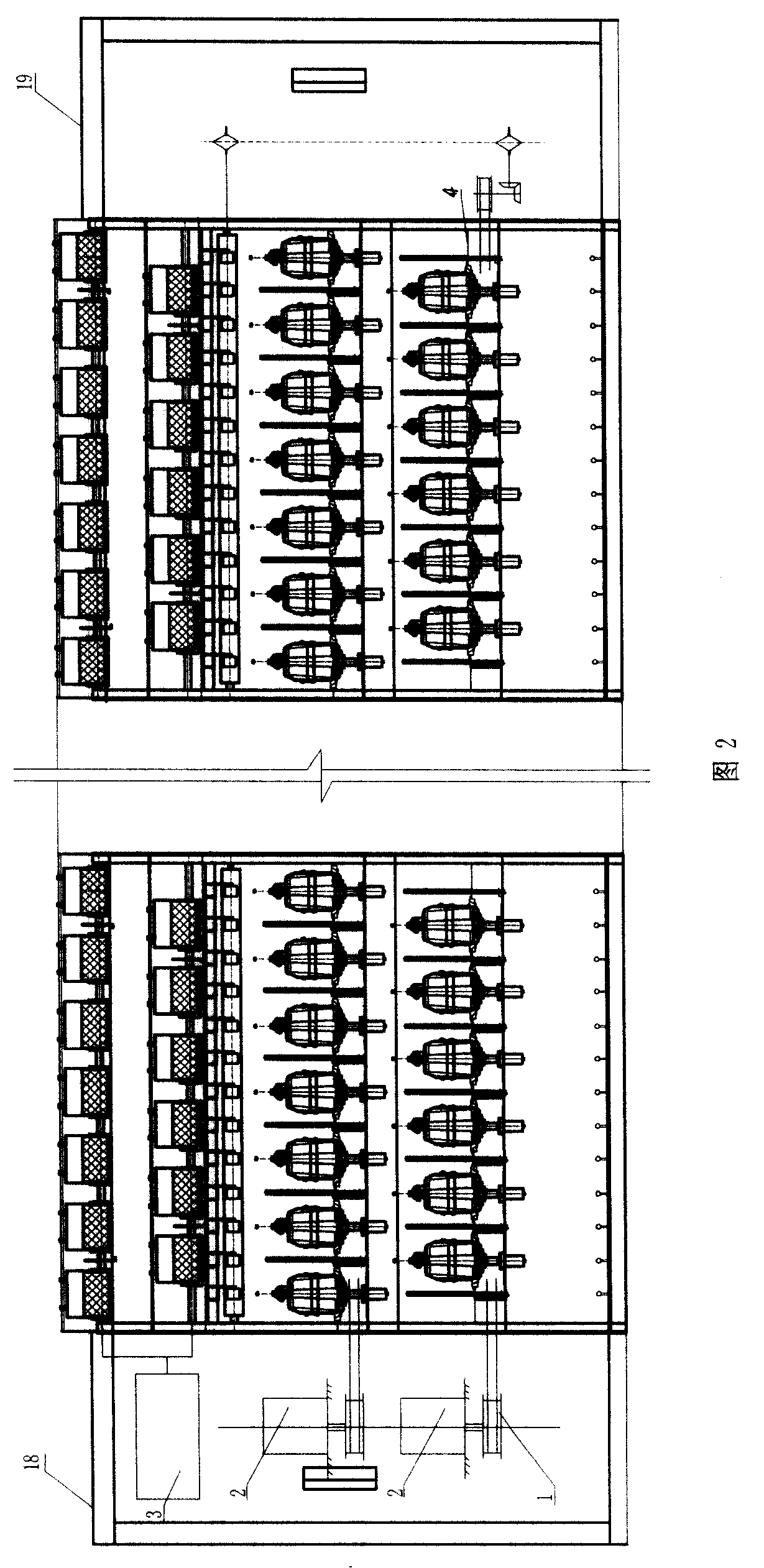
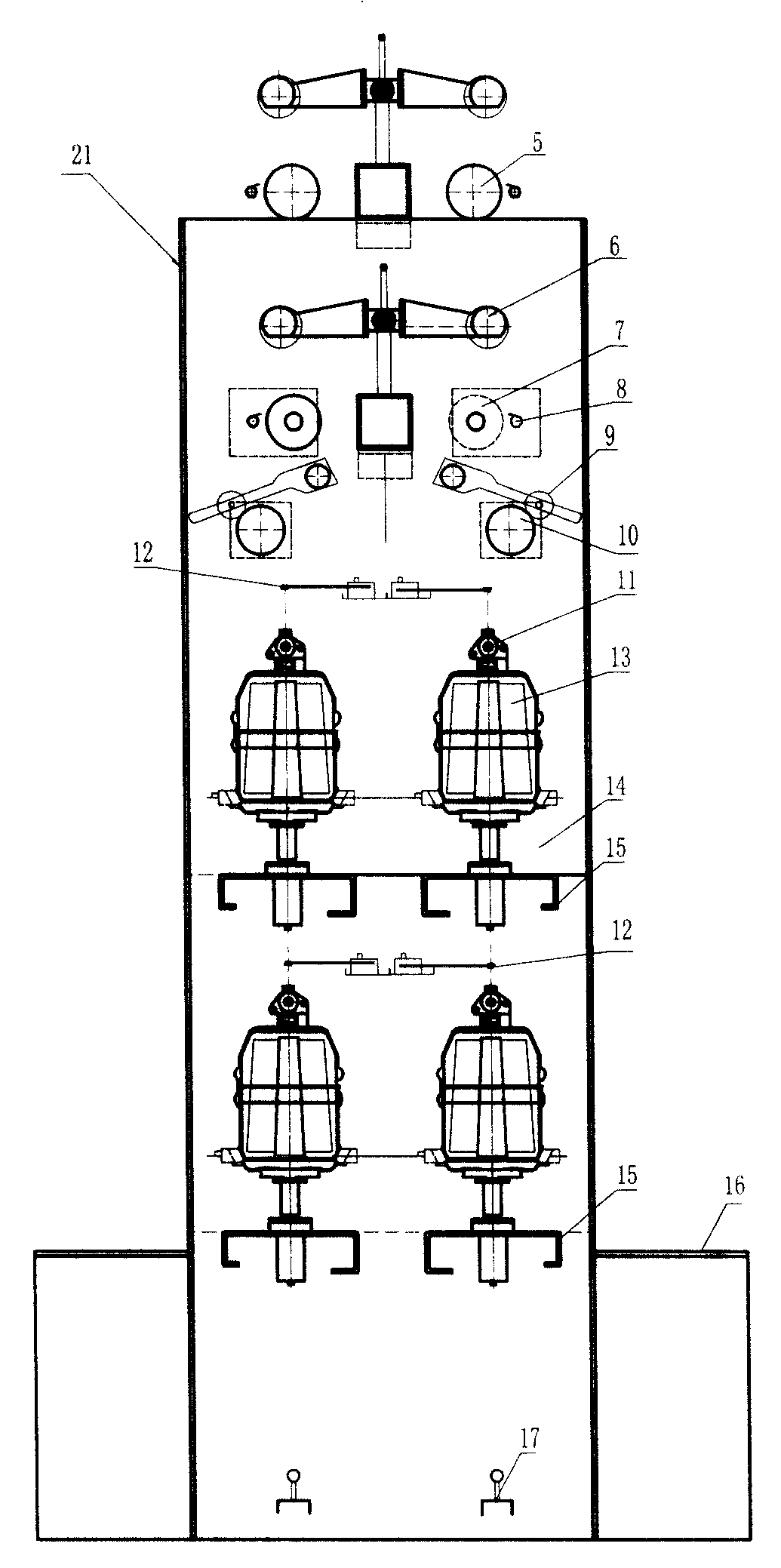

Image

  • Direct twisting type twisting technique
  • Direct twisting type twisting technique
  • Direct twisting type twisting technique

Examples


Embodiment 1

[0049] Process of the present invention is:

[0050] A. The first yarn bobbin is loaded into the yarn pot, and the first yarn is pulled out from above the yarn pot, and the tension is controlled by the tensioner;

[0051] B. The second bobbin is placed on the creel at the lower end of the first bobbin, and the second yarn enters the hollow spindle through the thread guide mechanism, and the tension is controlled by a tensioner before passing through the twisting disc on the hollow spindle. With the rotation of the hollow spindle, it is thrown out of the hollow spindle, and the upper end is wrapped with the first yarn to rotate around the yarn pot in the form of a balloon, and the tension of the first yarn and the second yarn in the balloon state increases or decreases correspondingly with the change of the spindle speed ;

[0052] C. The first and second yarns are combined into one strand at the top of the balloon. When the two yarns are plyed, the tension of the two yarns is...

Embodiment 2

[0054] As shown in Figure 2, image 3 As shown, in the present invention, each spindle position on the twisting machine is provided with at least two layers of spindle assemblies up and down, a first yarn bobbin and at least two rows of second yarn bobbins in front and back, and multi-layer operations are carried out on one spindle position.

Embodiment 3

[0056] Such as figure 1 ,figure 2, image 3 Shown, the yarn running route of the present invention is:

[0057] The first yarn: bobbin, first tensioner, ply yarn guide;

[0058] The second yarn: yarn bobbin, yarn guide mechanism, second tensioner, yarn guide, spindle center hole, spindle core-embedded steering, twisting disc, ply yarn guide;

[0059] After plying: Roller traction, bobbin forming mechanism, including traversing screw rod, friction drum, winding tube.


PUM


Abstract

The invention discloses a direct twisting technique which is applicable to industrialized direct twisting of combination twisting, in particular to the direct twisting of fine denier yarns of embroidery thread, nylon, polyester, rayon and sewing thread. The procedures of the invention are that: on a twisting machine, a first tube of yarn is directly up-drawn; a second tube of the yarn driven by aspindle rotates around the first tube; two tubes of the yarns are twisted together at the circumrotation finial; the yarns are wound into finished products of core-spun yarns. After being stranded bythe direct twisting technique, the single yarn has no twist, thereby the strain of the two strings of silk can be easily controlled to obtain satisfying strength.

Description

technical field [0001] The invention belongs to the field of textiles, and specifically relates to a twisting process, especially a direct combined twisting process, which is suitable for twisting embroidery threads, nylon, polyester, rayon, sewing threads and the like. Background technique [0002] Twisting in the traditional sense refers to the twisting of two or more strands of yarn. The twisting process (roving, spun yarn, twisted thread) is generally: holding point (the front roller of the input strand) → twisting point (the flyer , spindle, traveler) → winding point (the package is the second holding point). At present, the scope of twisting includes a variety of yarn processing and finishing processes. Of course, all crafts have to add "twist". The most common twisting processes are: single-yarn twisting, ply-yarn twisting, covering, structural twisting, and combinations thereof. [0003] Single Yarn Twisting: In this process, twist is added to a single yarn. Usua...

Claims


Application Information

Patent Timeline
Patent Type & Authority Patents(China)
IPC IPC(8): D01H1/00D01H7/00D01H13/10D02G3/22D02G3/36
Inventor 杨学利梁建军
Owner 北京市文化科技融资租赁股份有限公司
Learn More