Star loaded camera spacing deformation geometric image correction method

A space image and distortion correction technology, applied in the field of image processing, can solve the problems of inapplicability and impossibility of arbitrarily changing space-borne cameras, and achieve the effects of convenient re-measurement, high correction accuracy, and avoiding parameter drift

Inactive Publication Date: 2008-08-20
BEIHANG UNIV
View PDF0 Cites 55 Cited by
  • Summary
  • Abstract
  • Description
  • Claims
  • Application Information

AI Technical Summary

Problems solved by technology

However, since the motion of the satellite is limited by its orbit, it is impossible to change it arbitrarily. At the same tim...

Method used


Image

  • Star loaded camera spacing deformation geometric image correction method
  • Star loaded camera spacing deformation geometric image correction method
  • Star loaded camera spacing deformation geometric image correction method

Examples


Embodiment Construction

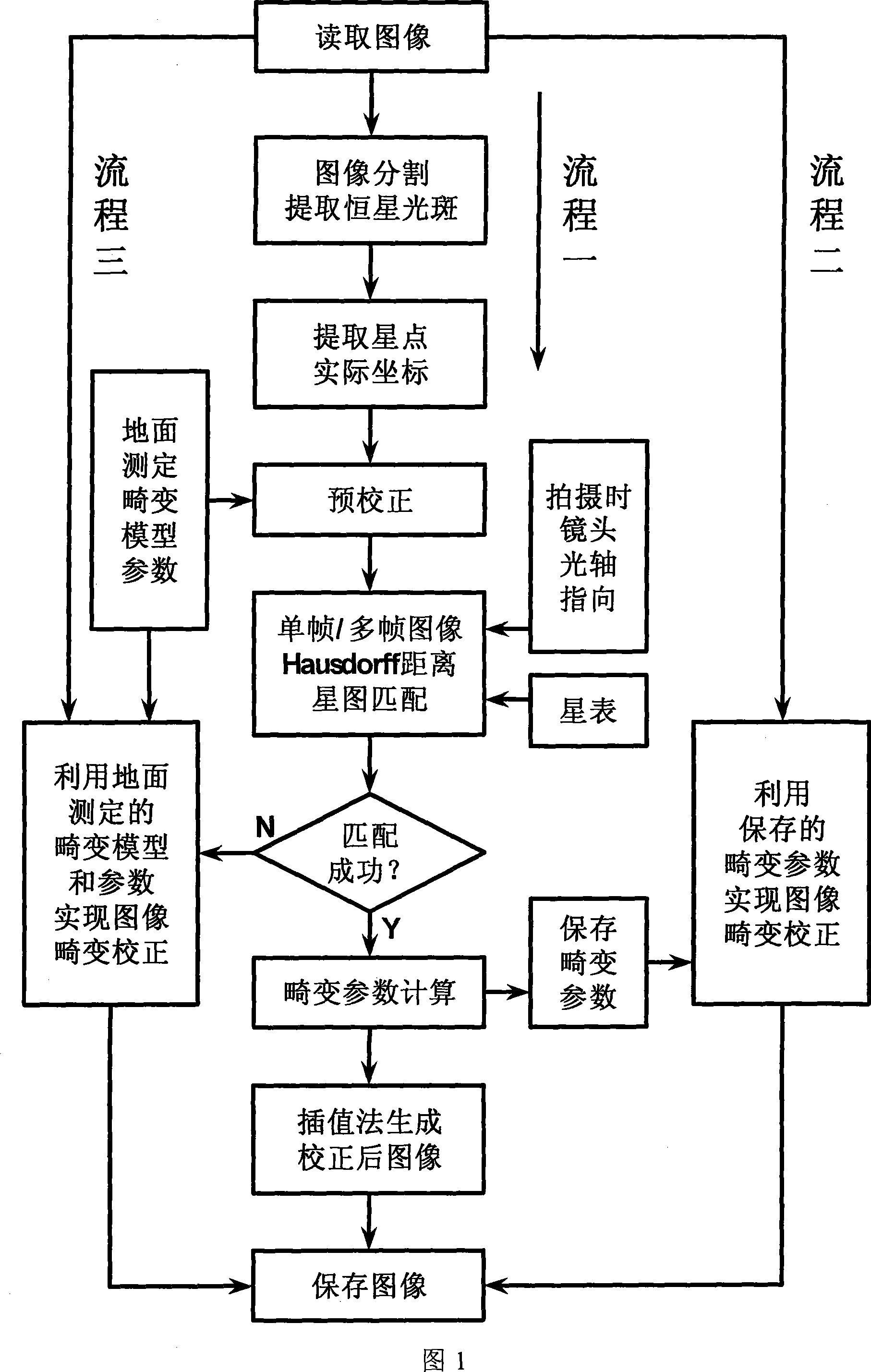
[0024] As shown in Figure 1, the steps of the present invention are as follows:

[0025] 1. Extract stellar spots through image segmentation

[0026] First, read in enough frames of the starry sky background image to ensure that there are more than 10 stars in the image, and secondly separate the stellar spots by image segmentation. In the present invention, the improved Otsu threshold method is used for image segmentation, and the specific process is as follows:

[0027] (1) Let T min Is the average gray value of the image, even if the size of the image is M×N, the gray value of the point (i, j) on the image is G(i, j), then T min = Σ i = 1 M Σ j = 1 N G ...


PUM


Abstract

The present invention provides a Satellite-bone camera space image distortion correction method based on the stellar map matching, the stellar point on the image is used as referecen point, achieving the distortion correction, including following steps: (1)image segmentation, extracting the stellar facula in the image; (2) calculating areal coordinates of each facula by the centroid method, as a real coordinate; (3) processing pre-correction according to the deformation parameter obtained by the ground standardization of the camera; (4) processing stellar map matching by single frame or multiple frames Hausdorff distance stellar map matching method, calculating academic coordinate corresponding to the practical coordinate; (5) calculating deformation parameter of the image by the corresponding relation between the practical coordinate and the academic coordinate; (6) obtaining corrected image by the three steps fitting of a polynomial and interpolation method. In addition, the invention aiming at correctoon impact of the camera plain shaft point system error, provides a adaptive compensation method. The invention has small operation, evident image correcting effect, and effectively preventing the impact of the correction caused by the image noise and the input system error.

Description

Technical field [0001] The invention mainly relates to a distortion image geometric correction method in the field of image processing, aiming at the distortion of the space image taken by a satellite-borne camera. Background technique [0002] Since the actual lens composition process of the camera is difficult to achieve the ideal lens imaging effect, the tangential magnifications at different points on the vertical main axis plane of the image side are generally not exactly the same, resulting in camera distortion. It is generally believed that the distortion of the camera is mainly radial distortion and tangential distortion. The radial distortion is due to the error of the curvature of each lens, while the tangential distortion is attributed to the lack of coincidence of the optical spindles of the lenses. [0003] Although the spaceborne CCD camera can be accurately calibrated on the ground, due to its long focal length, high resolution, long operating distance, large light...

Claims


Application Information

Patent Timeline
IPC IPC(8): G06T5/00
Inventor 秦世引张淳
Owner BEIHANG UNIV
Why Eureka
Try Eureka