Motor-driven wheel driving apparatus

A wheel-driven, electric technology, applied in the direction of gear transmission, electromechanical devices, electric vehicles, etc., can solve the problems of limiting installation space and increasing space, and achieve the effect of improving durability

Inactive Publication Date: 2008-08-20
NTN CORP
View PDF1 Cites 43 Cited by
  • Summary
  • Abstract
  • Description
  • Claims
  • Application Information

AI Technical Summary

Problems solved by technology

[0012] In such a conventional electric wheel drive device 51, although such a gear reducer 55 can be easily assembled with various components, on the other hand, in order to re

Method used


Image

  • Motor-driven wheel driving apparatus
  • Motor-driven wheel driving apparatus
  • Motor-driven wheel driving apparatus

Examples


Embodiment 1

[0033] Hereinafter, embodiments of the present invention will be described in detail with reference to the drawings.

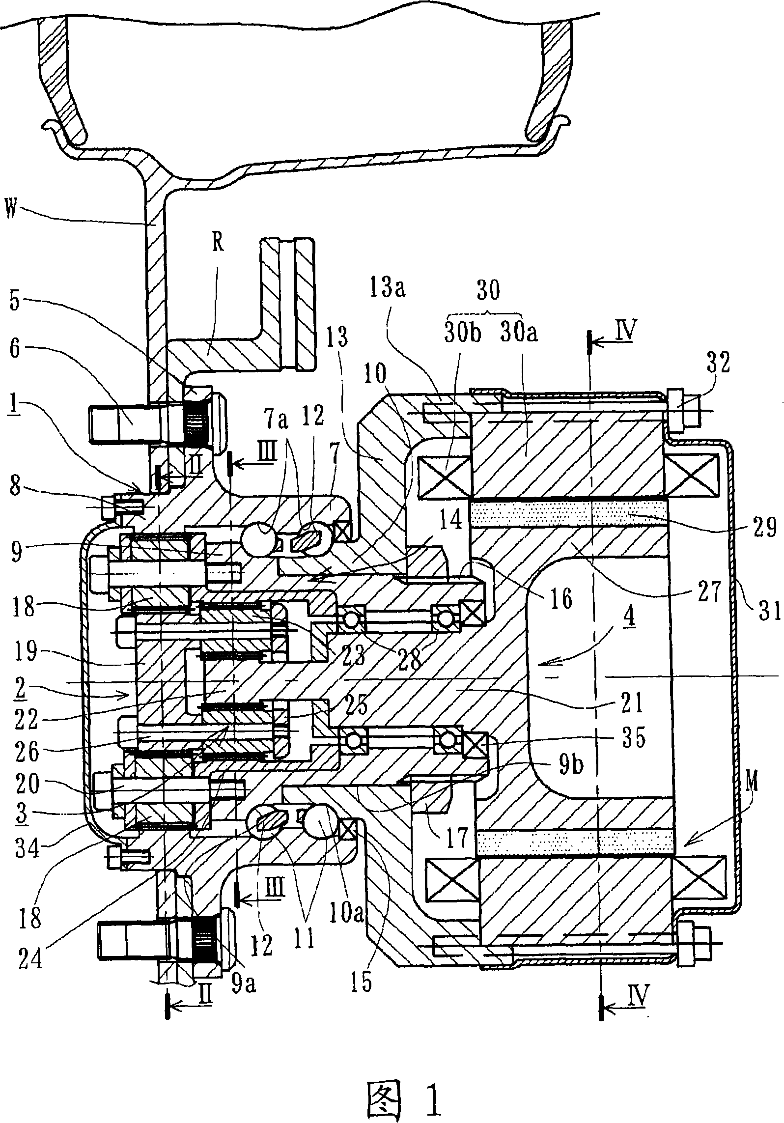
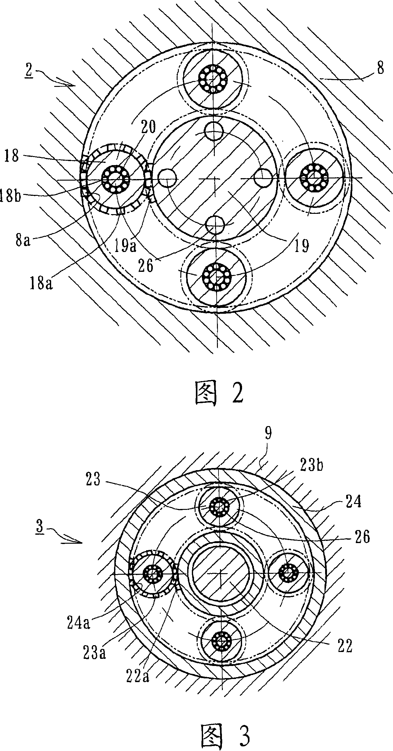
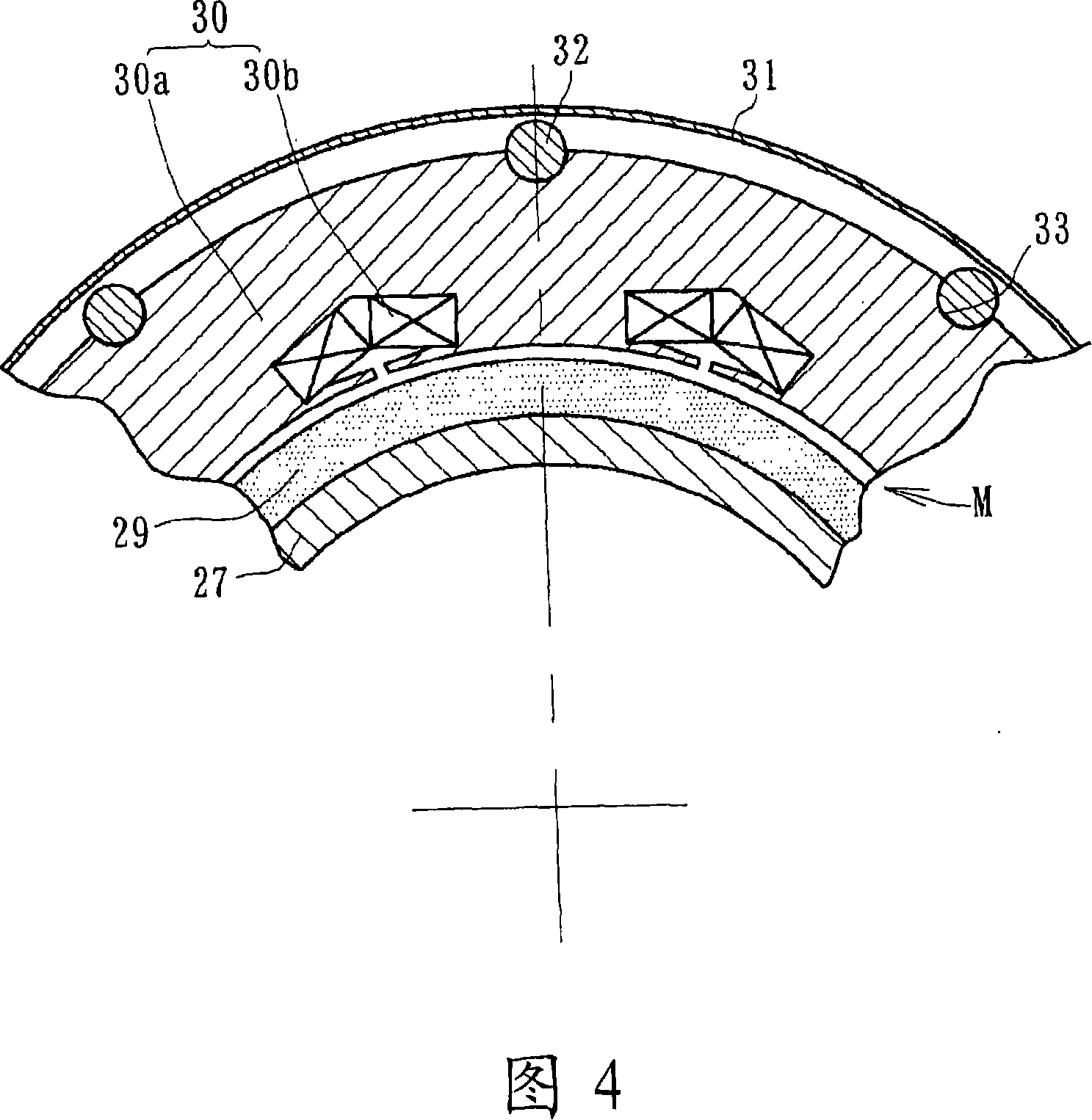
[0034] Fig. 1 is a longitudinal sectional view showing the first embodiment of the electric wheel drive device of the present invention, Fig. 2 is a cross-sectional view along the line II-II of Fig. 1 , and Fig. 3 is a cross-sectional view along the line III-III of Fig. 1 Cross-sectional view, Fig. 4 is a cross-sectional view along line IV-IV of Fig. 1 . In addition, in the following description, in the state mounted on the vehicle, the side closer to the vehicle outer side is referred to as the vehicle outer side (left side in the drawing), and the side closer to the center is referred to as the vehicle inner side (right side in the drawing). side).

[0035] The electric wheel drive device mainly includes: a wheel bearing 1; a first planetary reducer 2 disposed radially inside the wheel bearing 1; a second planetary reducer 3 connected to the first planetary...

Embodiment 2

[0052] Fig. 5 is a longitudinal sectional view showing a second embodiment of the electric wheel drive device of the present invention. Furthermore, this embodiment is only different in the structure of the planetary reducer in the first embodiment described above, more specifically, the structure of the first planetary reducer; Functional parts are denoted by the same reference numerals, and repeated explanations are omitted.

[0053] The first planetary reducer 2' constitutes a so-called planetary type planetary reducer, which is provided with: a first internal gear (output unit) 8' integrally formed with a first inner ring member 9' and formed with internal teeth 8a; four first planetary gears (planetary units) 18, which are formed with external teeth 18a meshing with the internal teeth 8a of the first internal gear 8', and perform planetary motion along the inner circumference of the first internal gear 8'; and A sun gear (input unit) 19 formed with external teeth 19 a me...

Embodiment 3

[0056] Fig. 6 is a longitudinal sectional view showing a third embodiment of the electric wheel drive device of the present invention. In addition, this embodiment is a modified example of the first embodiment described above, and is constituted by a one-stage planetary reducer. In addition, the same reference numerals are attached to the same members and the same parts or parts having the same functions as those in the embodiment described above, and overlapping descriptions will be omitted.

[0057] The planetary speed reducer in this electric wheel drive basically abolishes the second planetary speed reducer 3 in the first embodiment ( FIG. 1 ), and consists of the first planetary speed reducer 2 as one stage. This planetary reducer 38 constitutes a star-shaped planetary reducer in which the first internal gear 8 rotates by itself, and includes: a first internal gear (output unit) 8 integrally formed on the outer member 7 and formed with internal teeth 8a; a first planetar...


PUM


Abstract

An electric wheel-drive device where a bearing for a wheel has improved durability, that is reduced in weight and size, and that has increased easiness of disassembling and assembling. The electric wheel-drive device has a drive section (4) having a double-row bearing (1) for a wheel, the bearing being provided with an outer member (7) having on its outer circumference a wheel installation flange (5) and also having an inner member (14) with a stator housing (13); first and second planetary reduction gears (2, 3) arranged radially inward of the bearing (1); and a circular cylindrical support member (27) for driving the planetary reduction gears (2, 3) and to which an electric motor (M) and a rotor section (29) are secured. The support member (27) is rotatably supported relative to the inner member (14) via a rolling bearing (28), and the rotation of the electric motor (M) is transmitted to the outer member (7) via the first and second planetary reduction gears (2, 3) to drive the wheel (W).

Description

technical field [0001] The present invention relates to an electric wheel drive device in which a wheel bearing, a speed reducer, and a motor are integrated, which are used in vehicles such as electric automobiles, golf carts, and forklifts. Background technique [0002] The electric wheel drive device is proposed to improve the driving efficiency when the wheels are driven by an electric motor. It is used for driving wheels of vehicles such as electric vehicles, and is configured to directly drive the wheels to rotate by the electric motor. However, in such an electric wheel drive device, since the electric motor requires a large output torque, it is necessary to use a large electric motor. This not only increases the cost but also increases the weight, making it difficult to sufficiently ensure the running performance of the vehicle. [0003] In this regard, an electric wheel drive device (in-wheel motor: In-wheel motor) with a speed reducer has also been proposed, which ...

Claims


Application Information

Patent Timeline
IPC IPC(8): B60K7/00F16C19/18F16C33/60F16H1/36F16H1/46H02K7/08H02K7/116
CPCB60K2007/0092H02K7/085H02K7/116B60K17/043F16H1/20B60K2007/0038F16H1/46F16C19/187B60K17/046H02K5/1735F16C19/55B60K7/0007F16H1/28B60L2220/44B60L2270/142B60L2270/145Y02T10/64
Inventor 铃木稔
Owner NTN CORP
Why Eureka
Try Eureka