Differential-pressure vacuum injection molding technique

A vacuum injection molding and process technology, which is applied in the field of plastic parts and can solve the problems of high scrap rate of plastic parts

Inactive Publication Date: 2008-08-27
SHANGHAI UNIV
View PDF0 Cites 8 Cited by
  • Summary
  • Abstract
  • Description
  • Claims
  • Application Information

AI Technical Summary

Problems solved by technology

The current rapid mold method can no longer adapt to such changes and requirements, especially the existing vacuum injection molding process, which is likely to cause high scrap rates of plastic parts such as thin-walled, transparent, mesh and complex shapes.

Method used


Image

  • Differential-pressure vacuum injection molding technique

Examples


Embodiment Construction

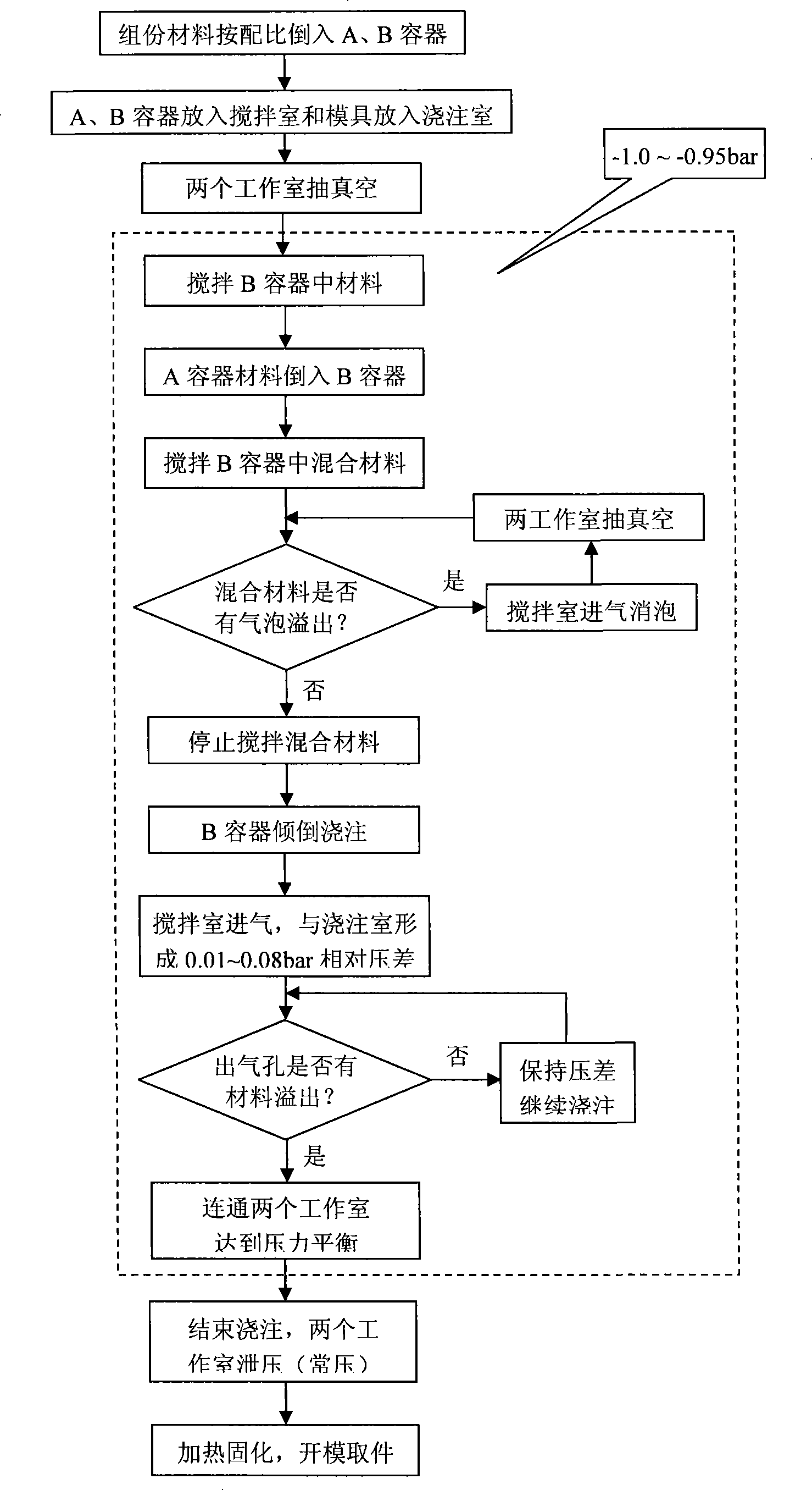
[0018] A preferred embodiment of the present invention is described in detail as follows in conjunction with accompanying drawing:

[0019] The main features of the differential pressure vacuum casting process are the differential pressure casting process during pouring and the pressure balance process after pouring. In order to implement the above process, the vacuum working chamber is divided into two parts, the stirring chamber and the pouring chamber, which are sealed and isolated from each other. Before pouring, the two working chambers are evacuated at the same time; during pouring, air is supplied to the mixing chamber, and a certain pressure difference is formed between the stirring chamber and the pouring chamber to complete the differential pressure pouring process. At the end of pouring, open the corresponding valve to connect the two working chambers to achieve air pressure balance and complete the pressure balance process.

[0020] The specific operation process ...


PUM


Abstract

The invention relates to a differential pressure vacuum injection molding process, which includes the steps of preparing two constituent materials, mixing, stirring, injecting, and heating for solidification. During the process of mixing and stirring the two constituent materials, circulating air admission for de-foaming is performed continuously, i.e. the vacuumizing process to eliminate the foams in the mixed constituent materials to avoid producing defective products; when injecting the evenly mixed constituent materials, the filling of the evenly mixed constituent materials is accelerated by the pressure difference between a stirring chamber and an injecting chamber; when the mixed constituent materials overflow all air outlets, the stirring chamber and the injecting chamber quickly reach a pressure balance to prevent too many mixed constituent materials from overflowing. The injection molding process is suitable for producing compact, thin-walled, transparent and meshed plastic parts with few or no air holes and complicated shapes.

Description

Technical field: [0001] The invention relates to a process method of differential pressure injection molding in a vacuum environment, which is suitable for manufacturing plastic parts such as thin-walled, transparent, mesh and complex shapes. Background technique: [0002] In the field of rapid design and manufacturing, with the increasingly fierce market competition, the requirements for new product development are getting higher and higher, and enterprises have higher and higher requirements for rapid tooling methods for new products. The current rapid tooling method can no longer adapt to such changes and requirements, especially the existing vacuum injection molding process, which is likely to cause high scrap rates of plastic parts such as thin-walled, transparent, mesh and complex shapes. In order to improve the injection molding quality of such parts in a vacuum environment and reduce the reject rate caused by air bubbles or insufficient filling, it is necessary to us...

Claims


Application Information

Patent Timeline
Patent Type & Authority Applications(China)
IPC IPC(8): B29C39/44B29B7/86
Inventor 胡庆夕尤飞姚远林柳兰徐高春陆齐罗兴剑
Owner SHANGHAI UNIV
Why Eureka
Try Eureka