

Pump body assembly and compressor
A pump body and component technology, which is applied in the field of compressors, can solve problems such as insufficient back pressure of the sliding vane, and achieve the effects of improving stability, reducing leakage problems, and good lubrication effect
- Summary
- Abstract
- Description
- Claims
- Application Information
AI Technical Summary
Problems solved by technology
Method used
Image

Examples
Embodiment 1
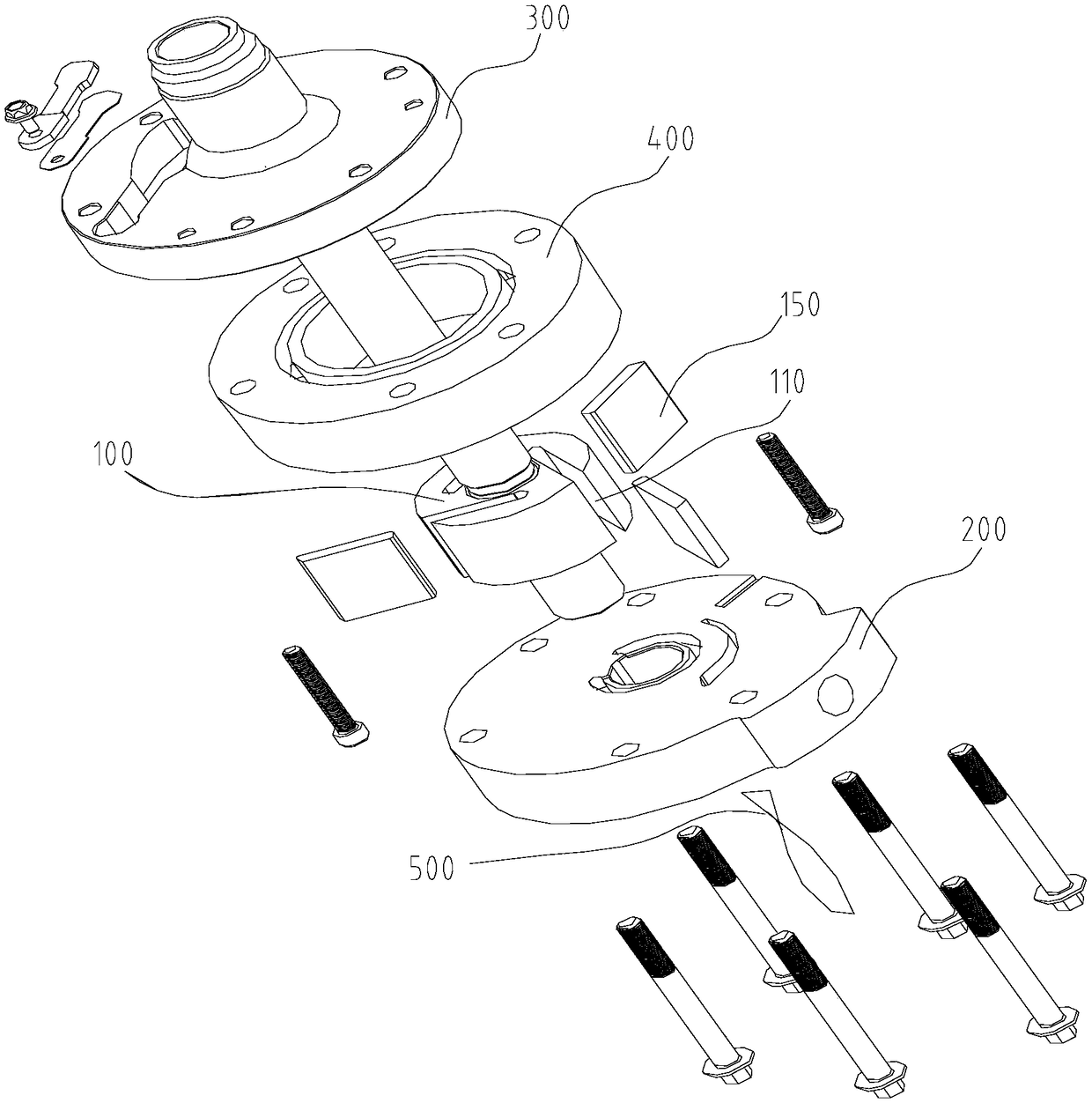
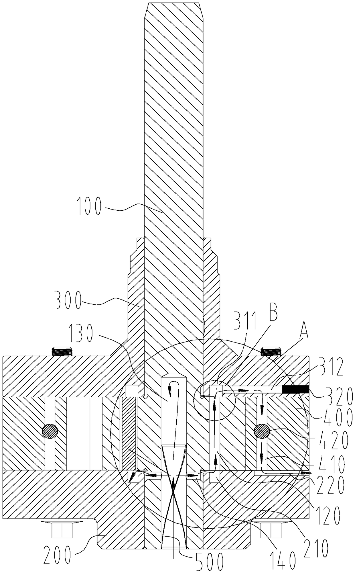
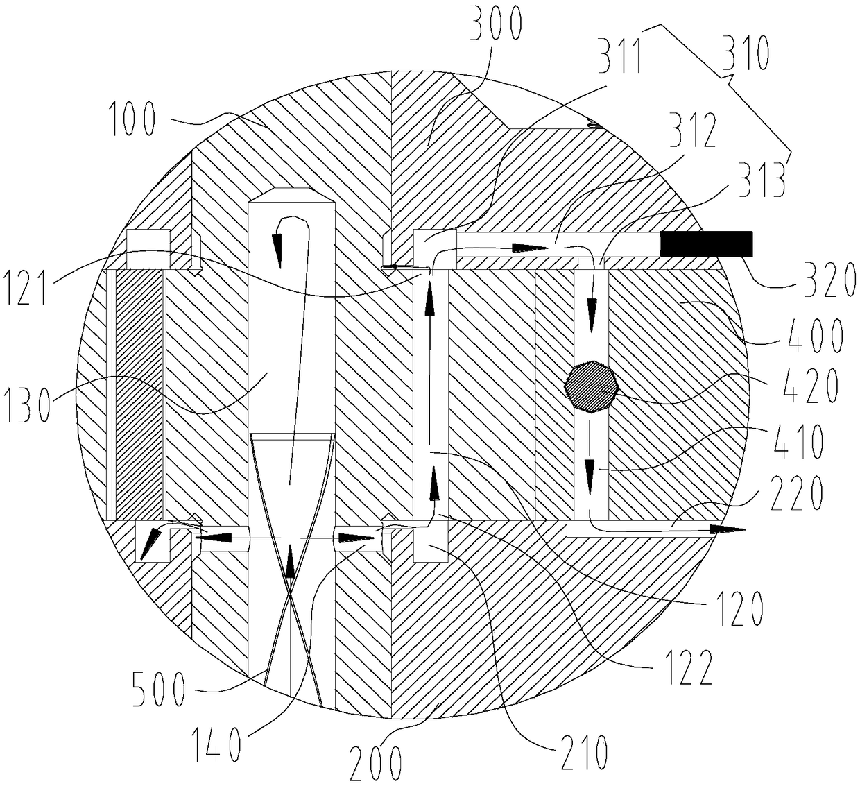
[0042] Such as Figure 1 to Figure 12 As shown, the pump body assembly includes a main shaft 100, the main shaft 100 has a sliding vane groove 110, the tail end of the sliding vane groove 110 is a back pressure oil chamber 120, the back pressure oil chamber 120 is at least a part of the oil channel, the back pressure oil chamber The oil outlet 121 is located on the top of the back pressure oil chamber 120, and the position of the oil inlet 122 of the back pressure oil chamber is lower than the position of the oil outlet 121 of the back pressure oil chamber, so that the lubricating medium enters through the back pressure oil chamber. The oil port 122 enters the back pressure oil chamber 120 and flows out from the top of the back pressure oil chamber 120 after filling the back pressure oil chamber 120 .
[0043]Since the tail end of the sliding vane groove 110 is the back pressure oil chamber 120, the lubricating medium can be injected into the back pressure oil chamber 120 to p...
Embodiment 2
[0060] The difference from Embodiment 1 is that the structure of the lower flange 200 is different.
[0061] Such as Figure 13 As shown, the pump body assembly also includes a lower flange 200. The lower flange 200 has an oil discharge hole 230 extending axially through. The bottom of the rolling element accommodation chamber 410 communicates with the top of the oil discharge hole 230. part of the roadway. In this way, the lubricating medium enters the oil discharge hole 230 from the bottom of the rolling element accommodation chamber 410, and flows back to the oil pool through the oil discharge hole 230, so as to realize the circulation of the lubricating medium. Through the continuous circulation process, each structure is fully lubricated, and Take away the generated heat to ensure the reliability and stability of the pump body components.
Embodiment 3
[0063] The difference from Embodiment 1 is that the structure of the lower flange 200 is different.
[0064] Such as Figure 14 As shown, the pump body assembly also includes a lower flange 200, and the surface of the lower flange 200 facing the back pressure oil chamber 120 is provided with an oil discharge communication groove 240; the bearing cylinder 400 includes: an axial oil discharge channel 430, rolling The bottom of the housing cavity 410 communicates with the bottom of the axial oil discharge passage 430 through the oil discharge communication groove 240; the radial oil discharge passage 440, the top of the axial oil discharge passage 430 communicates with the bearing cylinder 400 through the radial oil discharge passage 440 The outer peripheral surface of the shaft is connected, and the axial oil discharge passage 430 and the radial oil discharge passage 440 are part of the oil passage. In this way, the lubricating medium enters the oil discharge communication groo...
PUM
 Abstract
Description
Claims
Application Information