Blow-moulding device for composite plastic bottle and method for manufacturing composite plastic bottle

A technology for composite plastics and blow molding devices, which can be applied to other household appliances, household appliances, applications, etc., and can solve problems such as inability to meet large-scale production, low production efficiency, and insufficient quality of high-barrier composite plastic bottles, and achieve simple structure , high production efficiency and low cost

Inactive Publication Date: 2008-08-27
肖曼华
View PDF0 Cites 4 Cited by
  • Summary
  • Abstract
  • Description
  • Claims
  • Application Information

AI Technical Summary

Problems solved by technology

[0003] At present, the blow molding device used to produce high-barrier composite plastic bottles produces three-layer composite plastic bottles. Because the thickness of the barrier layer is not uniform enough, the quality of high-barrier composite plastic bottles is not good enough, and there is only one blow molding device. Dies, low production efficiency, unable to meet the needs of mass production

Method used


Image

  • Blow-moulding device for composite plastic bottle and method for manufacturing composite plastic bottle
  • Blow-moulding device for composite plastic bottle and method for manufacturing composite plastic bottle
  • Blow-moulding device for composite plastic bottle and method for manufacturing composite plastic bottle

Examples


Embodiment Construction

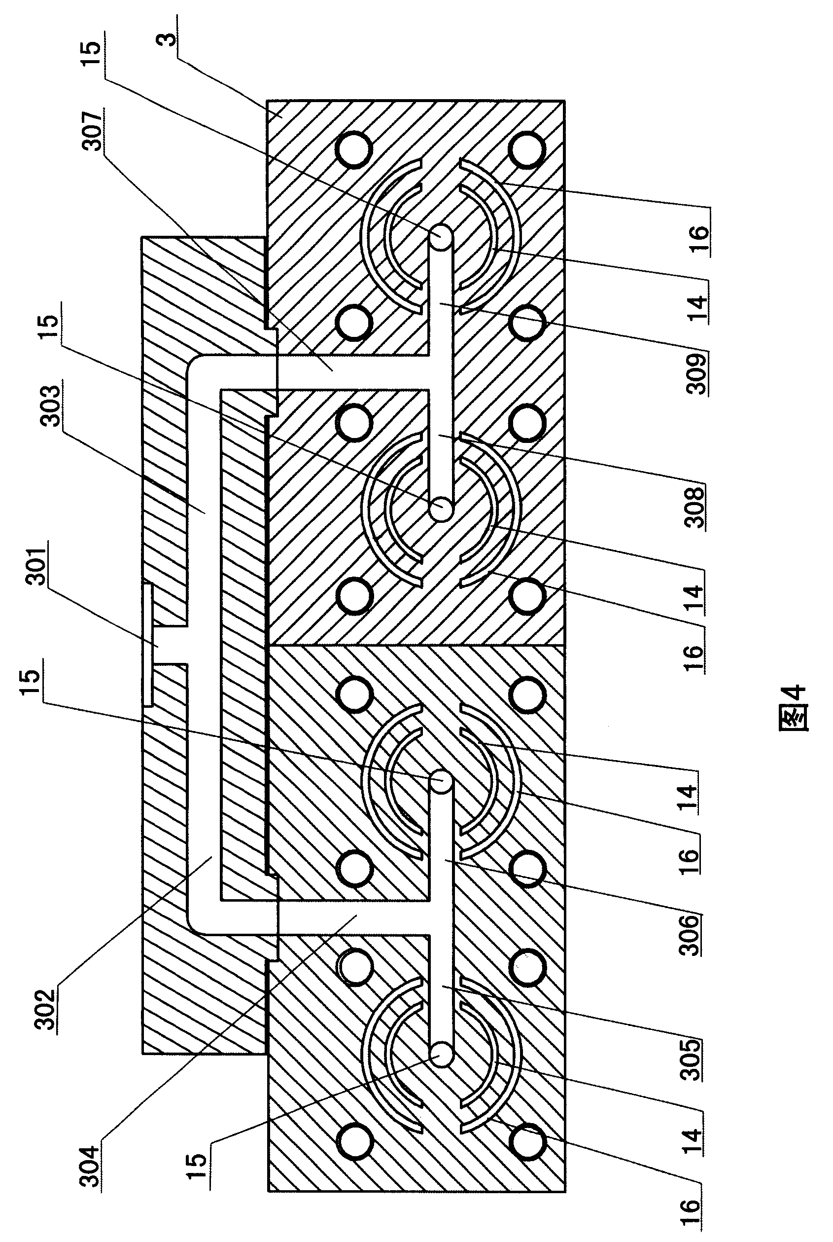
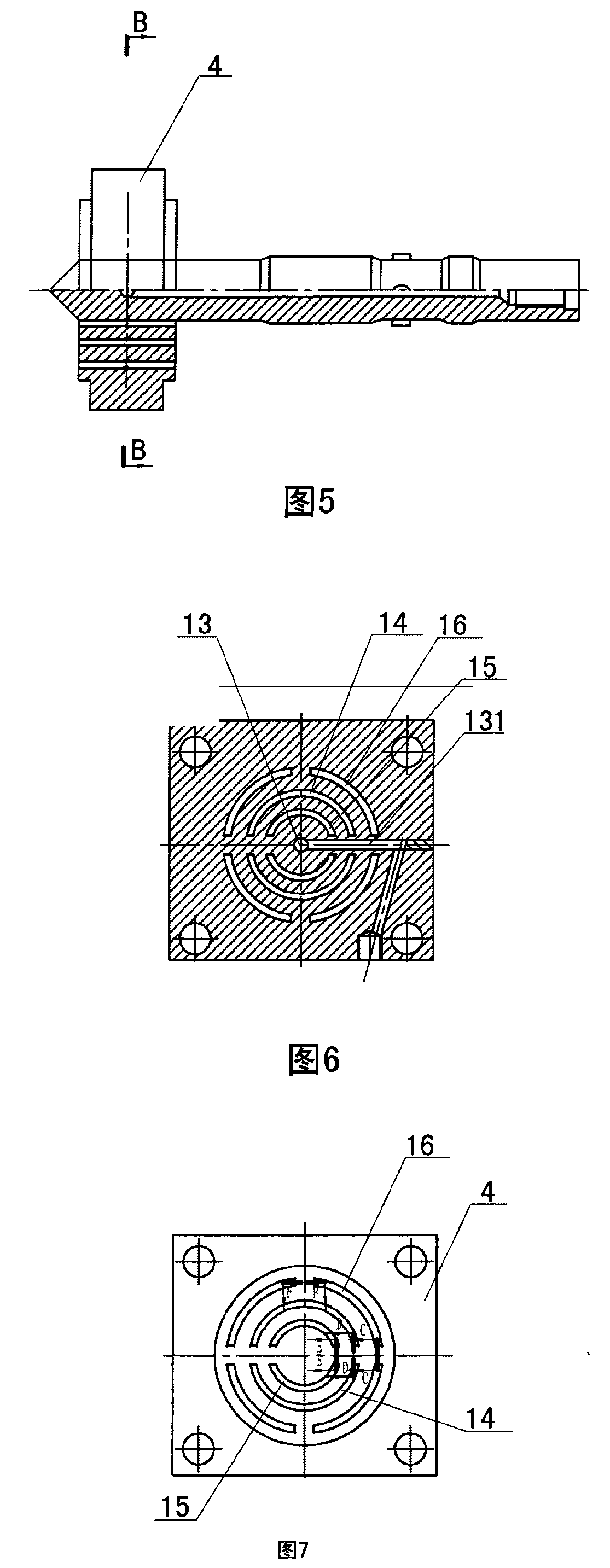
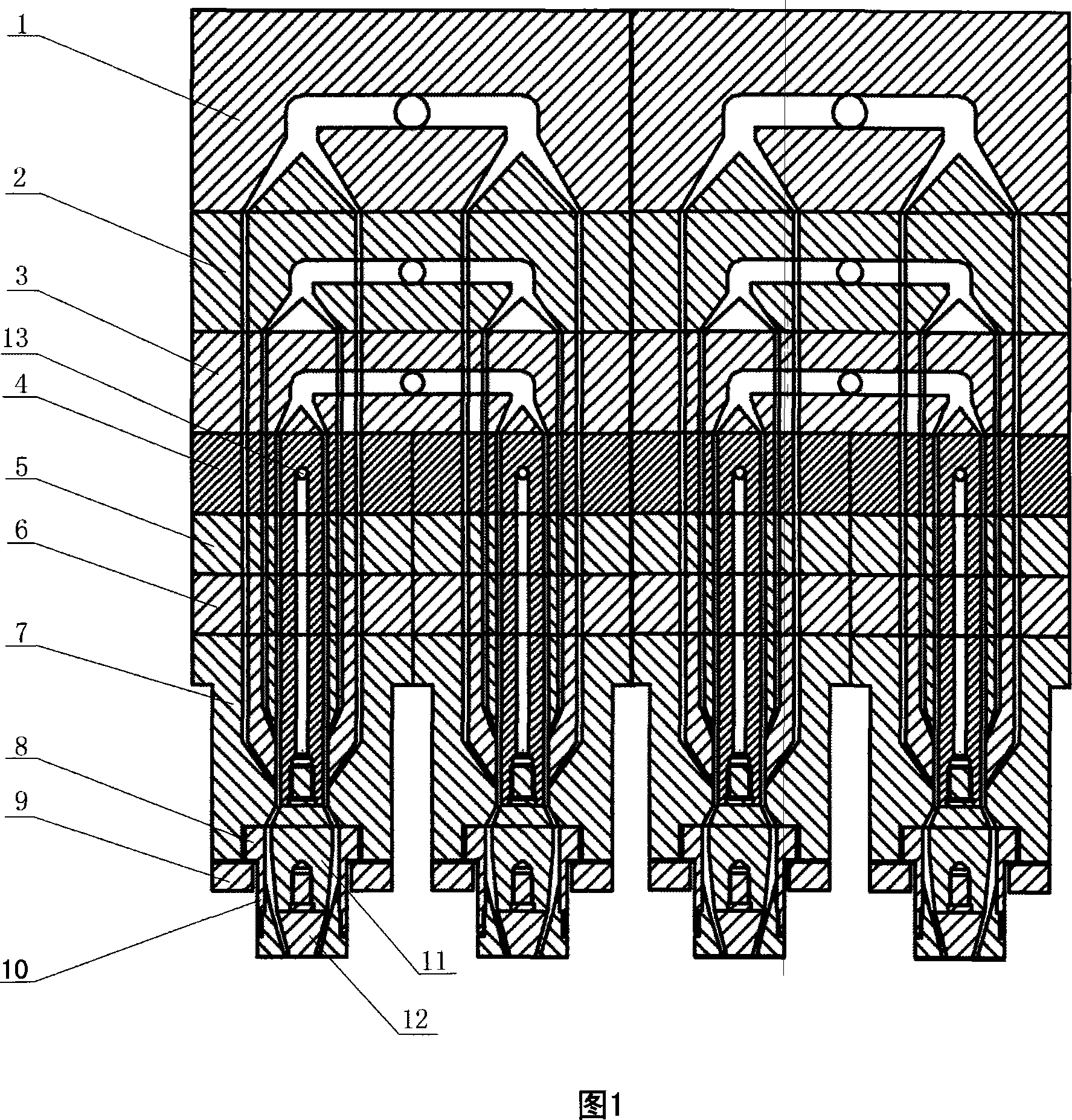
[0036] As shown in Figures 1-18, the composite plastic bottle blow molding device in this preferred embodiment includes a material distribution mechanism and four die heads, and the material distribution device is installed on the upper ends of all the die heads. Each die head includes a mold shell 7, a mold core, and a mold ring that is sleeved on the outside of the mold core and fixed at the lower end of the mold shell. The mold core is provided with an air inlet 13. The material diversion mechanism includes three sequentially stacked diverters. Blocks 1, 2, 3 (the number of the diverter blocks is equal to the number of layers of the high-barrier composite plastic bottle). Each distribution block is provided with a distribution pipeline, the distribution pipeline includes an inlet that can be connected with the material supply device, and the same number of distribution outlets as the number of die heads, and each distribution outlet is connected with the distribution channel...


PUM


Abstract

The invention discloses a composite plastic bottle blowing molding device, which comprises a material shunting mechanism and at least two die heads. The material shunting mechanism is installed on the upper ends of both die heads; each die head comprises a die casing, a die core and a die ring which is sheathed at the outer side of the die core and is fixed at the lower end of the die casing, and an air inlet is arranged on the die core; the material shunting mechanism comprises at least two shunting blocks which are piled up in sequence, a shunting pipeline is arranged inside in each shunting block, the shunting pipelines comprise inlets which can be connected with a material supplying device and shunting outlets with the amount being identical with that of the die heads, and each shunting outlet is connected with the shunting flow channel inlet of a die head. A composite plastic bottle manufacturing method comprises the following steps: at least two materials are evenly and respectively fed to each die head; the materials are respectively conveyed downward to the outlet opening of the die head through the shunting flow channel to be converged, are extruded from the lower end of the die head; and therefore the high-barrier composite plastic bottle is produced. The composite plastic bottle blowing molding device has the advantages of high production efficiency, simple structure, lower cost, and good operation effect.

Description

technical field [0001] The invention relates to a composite plastic bottle blow molding device for producing high-barrier composite plastic bottles and a manufacturing method for the composite plastic bottle. Background technique [0002] The current patented blow molding devices are all used to produce composite films, and these blow molding devices are not suitable for the production of composite plastic bottles. [0003] At present, the blow molding device used to produce high-barrier composite plastic bottles produces three-layer composite plastic bottles. Because the thickness of the barrier layer is not uniform enough, the quality of high-barrier composite plastic bottles is not good enough, and there is only one blow molding device. The die head has low production efficiency and cannot meet the needs of mass production. Contents of the invention [0004] The purpose of the present invention is to improve the prior art and provide a composite plastic bottle blow mol...

Claims


Application Information

Patent Timeline
Patent Type & Authority Applications(China)
IPC IPC(8): B29C49/04B29C47/12B29C47/06B29L22/00B29C48/30
Inventor 肖曼华
Owner 肖曼华
Why Eureka
Try Eureka