Method for improving quenching medium agitation strength
A quenching medium and strength technology, which is applied in heat treatment process control, manufacturing tools, heat treatment equipment, etc., can solve the problems of uneven heat conduction, weak flow velocity and impact force, etc., to solve the problem of weak flow velocity and impact force, simple implementation, Reduce the effect of uneven heat conduction
- Summary
- Abstract
- Description
- Claims
- Application Information
AI Technical Summary
Problems solved by technology
Method used
Image
Examples
Embodiment 1
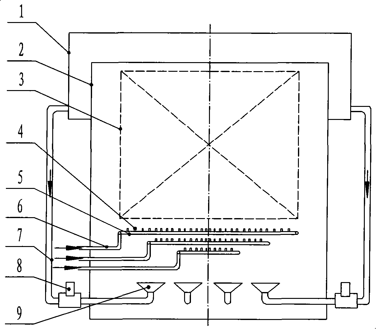
[0022] This example uses a quenching tank with a combination of pump stirring and compressed air stirring, see attached figure 1 . The quenching tank is composed of an overflow tank 1, a tank body 2, a quenching effective area 3, a compressed air nozzle 4, an annular compressed air pipe 5, a compressed air pipe 6, a liquid pipeline 7, a pump 8 and a liquid equalization device 9.
[0023] Mechanical stirring: The pump stirring of the quenching tank is to extract the medium from the overflow tank 1 under the action of the pump 8. The medium flows through the liquid pipeline 7 into the liquid equalization device 9 in the tank body 2 for flow equalization, and then the medium flows After the quenching effective area 3 is returned to the overflow tank 1, so that the flow of the medium is formed reciprocatingly, and multiple sets of pump stirring systems can be arranged in a quenching tank.
[0024] Stirring of compressed air: firstly, compressed air is passed into the compressed air p...
Embodiment 2
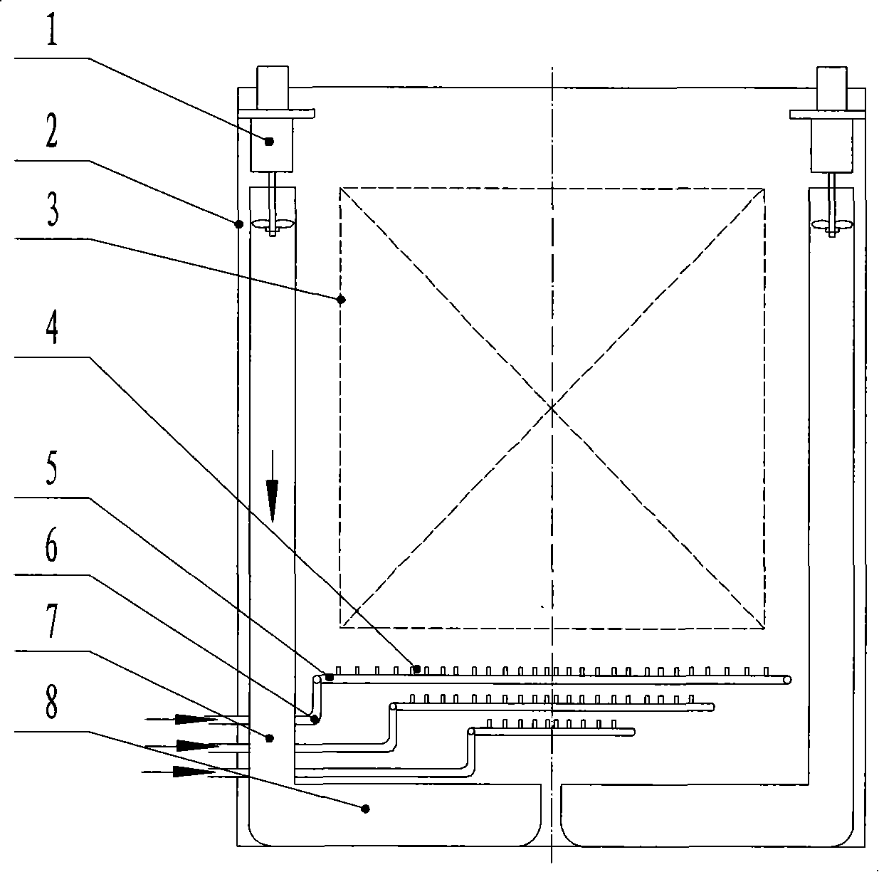
[0027] This example uses a quenching tank with a propeller agitator and compressed air agitating compound, see attached figure 2 . The quenching tank is composed of a propeller stirrer 1, a tank body 2, a quenching effective area 3, a compressed air nozzle 4, an annular compressed air pipe 5, a compressed air pipe 6, a flow guide tube 7 and a flow equalizing device 8.
[0028] Mechanical stirring: The propeller agitator 1 of the quenching tank pushes the medium from the upper part of the quenching tank to the bottom of the quenching tank through the guide tube 7, the medium is evened by the flow equalization device 8, and then the medium flows through the quenching effective area 3 and then returns to the quenching In the upper part of the tank, the flow of the medium is formed reciprocatingly, and multiple sets of propeller agitators 1 can be arranged in a quenching tank.
[0029] Stirring of compressed air: firstly, compressed air is passed into the compressed air pipe 6, and t...
Embodiment 3
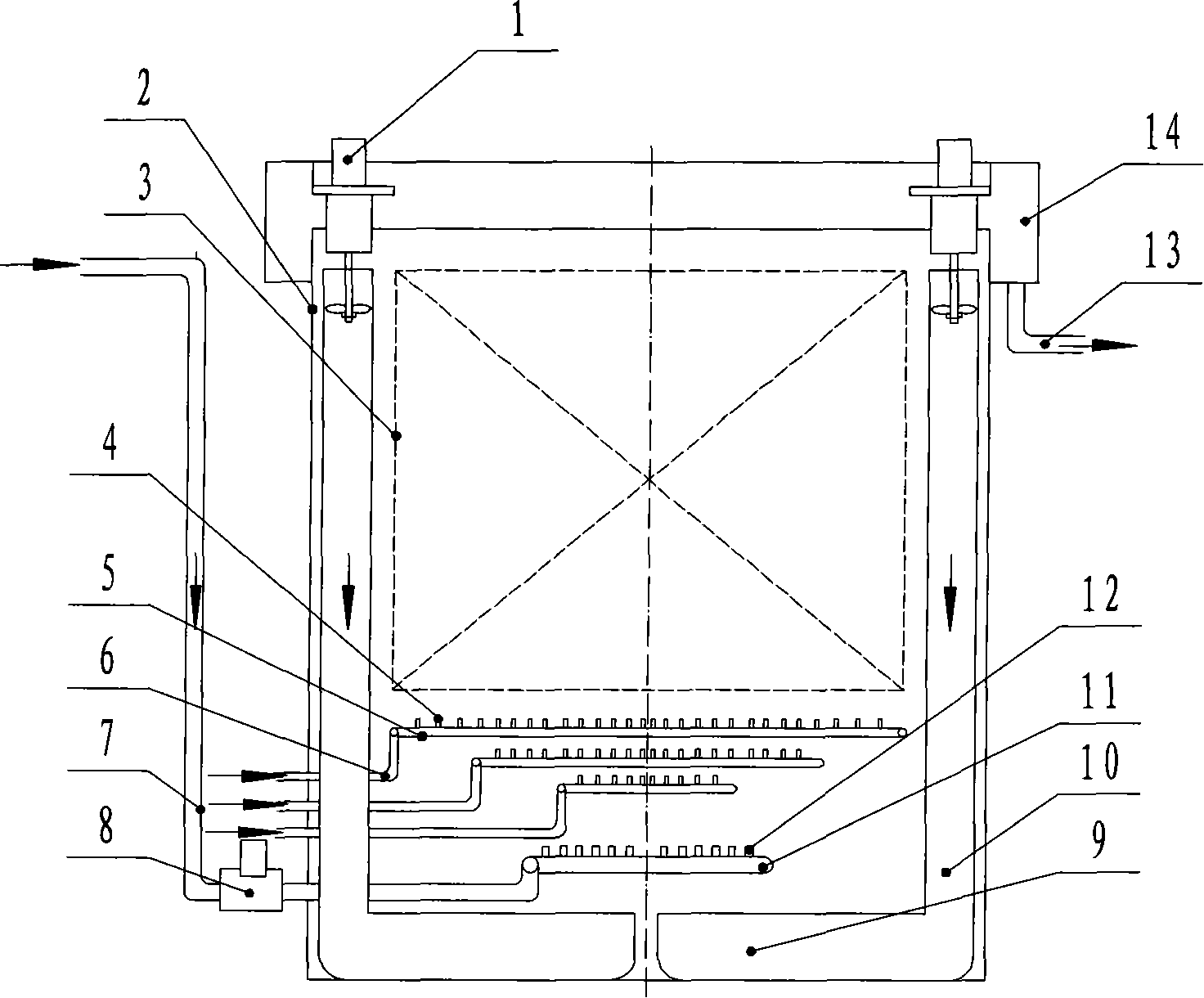
[0032] This example uses a quenching tank with a propeller agitator, pump agitation and compressed air agitation, see attached image 3 . The quenching tank consists of propeller agitator 1, tank body 2, quenching effective area 3, compressed air nozzle 4, annular compressed air pipe 5, compressed air pipe 6, pipeline 7, pump 8, flow equalization device 9, and guide tube 10 , The ring-shaped medium pipeline 11, the medium nozzle 12, the overflow pipe 13 and the overflow groove 14 are composed.
[0033] Mechanical stirring: The propeller stirrer 1 of the quenching tank pushes the medium from the upper part of the quenching tank to the bottom of the quenching tank through the guide tube 10, the medium is evened by the flow equalization device 9, and then the medium flows through the quenching effective area 3 and then returns to the quenching In the upper part of the tank, the flow of the medium is formed reciprocatingly, and multiple sets of propeller agitators 1 can be arranged in ...
PUM
 Abstract
Description
Claims
Application Information
 - R&D
- Intellectual Property
- Life Sciences
- Materials
- Tech Scout
- Unparalleled Data Quality
- Higher Quality Content
- 60% Fewer Hallucinations
Browse by: Latest US Patents, China's latest patents, Technical Efficacy Thesaurus, Application Domain, Technology Topic, Popular Technical Reports.
© 2025 PatSnap. All rights reserved.Legal|Privacy policy|Modern Slavery Act Transparency Statement|Sitemap|About US| Contact US: help@patsnap.com


