Pipe clamp structure

A technology of pipe clamps and pipes, applied in the direction of pipe supports, pipes/pipe joints/pipes, mechanical equipment, etc., can solve the problem of high cost of solid pipe clamps, achieve uniform fatigue distribution, strong bearing capacity, and enhanced bearing capacity Effect

Inactive Publication Date: 2008-08-27
GUANGDONG LIANSU TECH INDAL
View PDF0 Cites 1 Cited by
  • Summary
  • Abstract
  • Description
  • Claims
  • Application Information

AI Technical Summary

Problems solved by technology

[0002] Existing PVC pipe clamps, as attached image 3 , 4 shown, with image 3 Shown is the material-reducing pipe clamp structure, attached Figure 4 The shown is a solid pipe clamp structure, but whether it is solid or material-reducing type, there are obvious technical defects, that is, after the pipe clamp is installed on the wall and put on the pipe, the pipe clamp is directly stuck , interference fit to install the pipe, the clamp ring of the pipe clamp will be deformed, and the direction of the maximum deformation, as attached image 3 , 4 As shown by the arrow, one of the directions is consistent with the direction in which the gravity of the pipe and the medium in the pipe acts on the pipe clamp, that is, the main deformation stress coincides with the main external force direction, resulting in too concentrated stress on the pipe clamp at the coincidence point. As a result, the fatigue of this single place is intensified, the performance of bearing external force is insufficient during application, and the service life is reduced, etc. Therefore, the existing pipe clamp not only cannot withstand external force during application, but also has a short service life.
There are also problems such as high cost for solid pipe clamps

Method used


Image

  • Pipe clamp structure
  • Pipe clamp structure
  • Pipe clamp structure

Examples


Embodiment Construction

[0023] The present invention will be further described below in conjunction with the accompanying drawings.

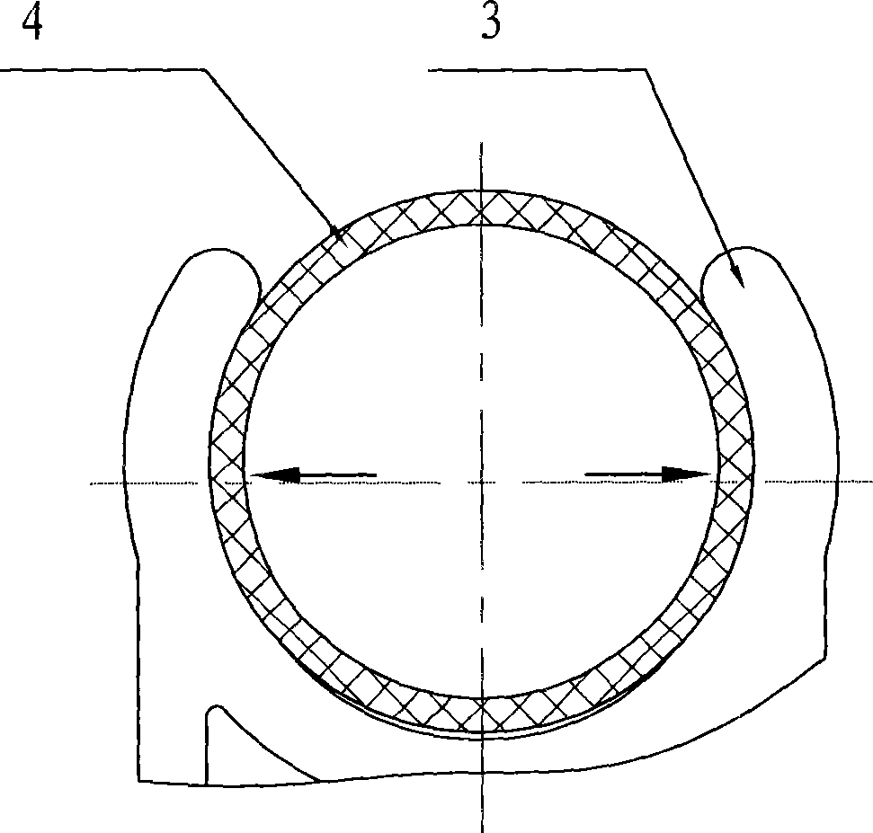
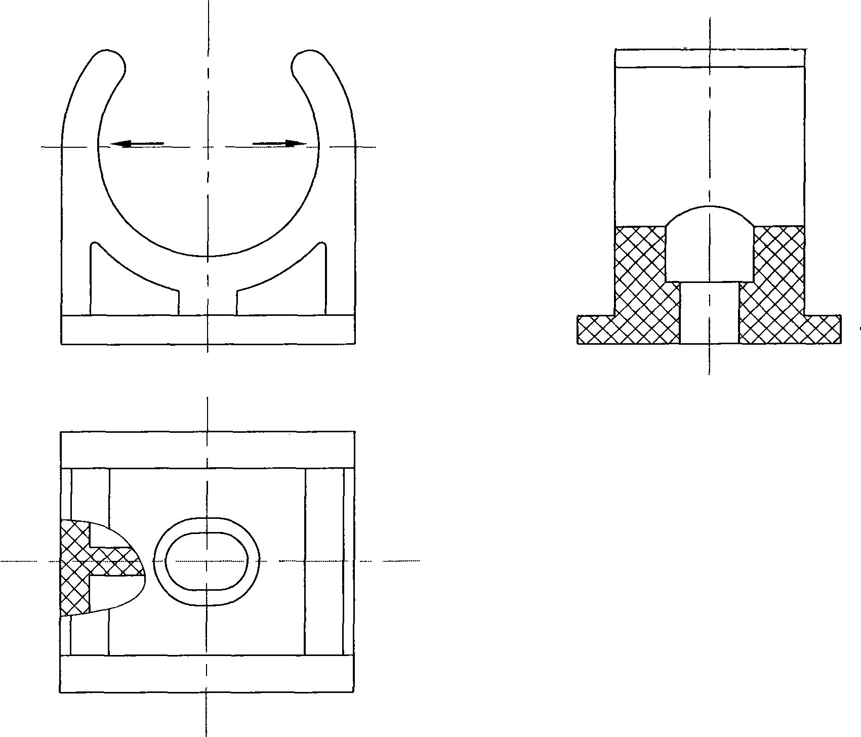
[0024] Structural schematic diagram of the present invention is attached figure 1 As shown, it includes a connection base 1, a support part 2 and a pipe clamp ring 3. One side of the connection base 1 is flush and close to the wall when installed. The other side of the connection base 1 is provided with a support part 2, and the pipe clamp ring 3 is arranged on the support part 2, and the geometric center symmetry line of the pipe clamp ring 3 forms an acute angle with the flush side of the connection base 1.

[0025] The structural feature of the present invention is that it has an acute inclined angle a, and its main direction of installation deformation force is reasonably staggered from the main direction of external force in the application after installation, such as figure 1 As shown, the arrow ① is the main deformation force, and the arrow ② is the main exte...


PUM


Abstract

The invention provides a pipe clamp structure which comprises a connecting base, a supporting part and a pipe retainer, wherein one side of the connecting base is abreast and clings a wall when mounted, the other side of the connecting base is provided with the supporting part, the pipe retainer is arranged on the supporting part, and the geometrical center symmetric line of the pipe retainer forms a sharp angle with the flush side of the connecting base. The pipe clamp structure enables the largest force distortion direction and the external force gravity direction to form a certain included angle, which allows more uniform force distribution and effectively prolongs the service life.

Description

technical field [0001] The invention belongs to the field of pipe clips, in particular to a PVC pipe clip structure. technical background [0002] Existing PVC pipe clamps, as attached image 3 , 4 shown, with image 3 Shown is the material-reducing pipe clamp structure, attached Figure 4 The shown is a solid pipe clamp structure, but whether it is solid or material-reducing type, there are obvious technical defects, that is, after the pipe clamp is installed on the wall and put on the pipe, the pipe clamp is directly stuck , interference fit to install the pipe, the clamp ring of the pipe clamp will be deformed, and the direction of the maximum deformation, as attached image 3 , 4 As shown by the arrow, one of the directions is consistent with the direction in which the gravity of the pipe and the medium in the pipe acts on the pipe clamp, that is, the main deformation stress coincides with the main external force direction, resulting in too concentrated stress on the ...

Claims


Application Information

Patent Timeline
Patent Type & Authority Applications(China)
IPC IPC(8): F16L3/04
Inventor 肖福全
Owner GUANGDONG LIANSU TECH INDAL
Why Eureka
Try Eureka