
System and method of multi-user multi-aerial transmission

A multi-user multi-antenna and user technology, which is applied to the system field of multi-user multi-antenna transmission to achieve the effect of spatial multiplexing

Active Publication Date: 2008-08-27
INST OF COMPUTING TECH CHINESE ACAD OF SCI
View PDF0 Cites 6 Cited by
  • Summary
  • Abstract
  • Description
  • Claims
  • Application Information

AI Technical Summary

Problems solved by technology

However, the existing technology is considered from a single physical layer or MAC (Media Access Control, media user access) layer, which cannot simultaneously meet the QoS requirements of each user and maximize the overall transmission capacity of the system. Therefore, it is necessary to jointly consider the physical layer and MAC At the physical layer, by estimating the channel state information of each user and combining the MAC layer parameters of each user, the cross-layer multi-user data transmission optimization in the multi-antenna system is realized.

Method used


Image

  • System and method of multi-user multi-aerial transmission
  • System and method of multi-user multi-aerial transmission
  • System and method of multi-user multi-aerial transmission

Examples


Embodiment 1

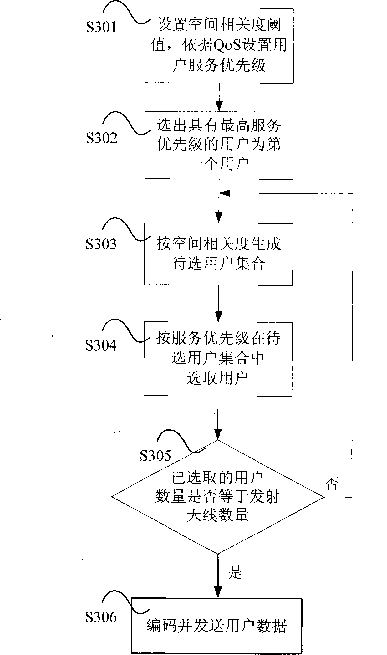
[0057] In Embodiment 1, users are selected according to the QoS level of the user's MAC layer and the spatial correlation between the selected users.

[0058] The specific method flow is as image 3 shown.

[0059] Step S301, according to the user's QoS requirements, it is divided into different QoS levels, each level corresponds to a service priority, and the higher the QoS level, the higher the corresponding service priority.

[0060] Step S302, selecting the user with the highest service priority as the selected user.

[0061] Step S303, obtain the channel matrix of each user, calculate the spatial correlation between the unselected user and the recently selected user according to formula 1 and formula 2, sort the spatial correlation, and select the spatial correlation lower than the spatial correlation threshold The unselected users constitute the user set to be selected.

[0062] If the user set to be selected already exists before the formation, the original user set ...

Embodiment 2

[0068] In Embodiment 2, users are selected according to the length of the user service queue at the user MAC layer and the spatial correlation between selected users.

[0069] The specific method flow is as Figure 4 shown.

[0070] Step S401, according to the length of the service queue of the user, it is divided into different levels, each level corresponds to a service priority, and the longer the service queue length, the higher the corresponding service priority.

[0071] Step S402, selecting the user with the highest service priority as the selected user.

[0072] Step S403, obtain the channel matrix of each user, calculate the spatial correlation between the unselected user and the recently selected user according to formula 1 and formula 2, sort the spatial correlation, and select the spatial correlation lower than the spatial correlation threshold The unselected users constitute the set of users to be selected.

[0073] If the user set to be selected already exists...


PUM


Abstract

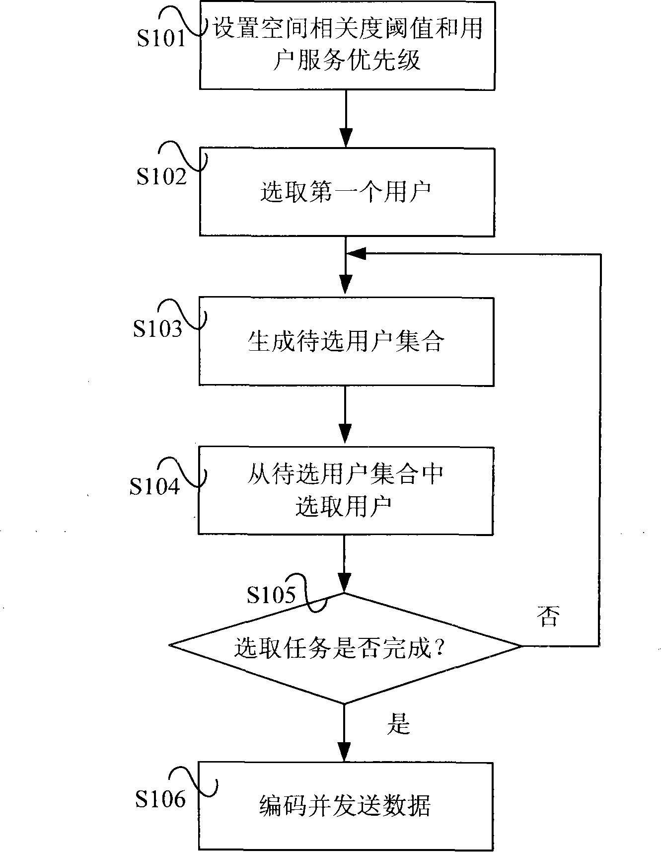
The invention discloses a multi-user multi-antenna transmission method which includes that; step1, the threshold of the space correlation degree is set; the service priority of the user is determined according to the parameters of the user media access control layer; step2, the user which has the highest priority is selected as the first selected user; step3, the space correlation degree of the unselected users and the lately selected user are computed; the users whose space correlation degrees are lower than the space correlation degree threshold construct a under-selected user set; step4, the user which has the highest priority in the under-selected set is selected as the selected user; step5, the step 3 and the step 4 are repeated to finish the selection of the user; the data of the selected user is encoded and transmitted; thereby, the over-layer optimum of the multi-user multi-antenna transmission is realized; the service requirement of the user is fulfilled; meanwhile, the interference among the users is reduced.

Description

technical field [0001] The present invention relates to the field of wireless communication multi-antenna technology, in particular to a multi-user multi-antenna transmission system and method. Background technique [0002] The MIMO (Multiple-input and Multiple-output) technology increases system capacity through spatial multiplexing and multi-user diversity, and has inherent advantages. [0003] In a multi-user MIMO system, it is assumed that M t antennas, and M r antennas, then the channel matrix of user k can be expressed as M r × M t The matrix H k , the signal received by user k is [0004] the y k =H k x+n k [0005] Among them, y k for M r The ×1 vector represents the signal received by user k, n k for M r The ×1 vector represents the interference noise received by user k, where x is M t The ×1 vector represents the signal sent by the base station. [0006] Through the SVD (Singular Value Decomposition, singular value decomposition) method, the wireless...

Claims


Application Information

Patent Timeline
Patent Type & Authority Applications(China)
IPC IPC(8): H04L1/06H04L1/00H04L12/56
Inventor 蒋海平杨育波田霖袁珏黄伊杨树伟石晶林
Owner INST OF COMPUTING TECH CHINESE ACAD OF SCI
Learn More